

Frequent alarms in the braking circuit of variable frequency systems? Uncertain about the correct resistance value and power rating for the 150W power range? This article focuses on ULV series braking resistors, outlining a three-step method—"Calculation-Verification-Installation"—to help you quickly determine the optimal parameter combination for a 150W braking resistor and avoid two common pitfalls: overheating and overcurrent.
As a core energy-consuming component in industrial drives,ULV braking resistorshave selection quality that directly determines the inverter's braking performance and system reliability. Especially in the prime 150W power range, engineers often experience premature equipment failure due to errors in resistance calculation or inadequate thermal design. Based on empirical data and industry standards, this article systematically breaks down the entire selection process.
Fundamentals of ULV Braking Resistors: Why 150W Is the Golden Power Range for Industrial Applications
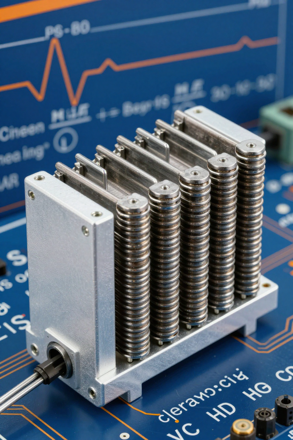
Braking resistors serve to dissipate regenerative energy in the variable frequency drive's energy consumption circuit. When the motor decelerates or lowers a load, the DC bus voltage of the VFD rises; once the braking unit turns on, it directs the excess energy into the resistor, converting it into heat.150W Braking ResistorIt precisely covers the mainstream braking requirements of 0.75kW–2.2kW inverters, making it the standard choice for medium and low-power drive systems.
The Core Role of Braking Resistors in the VFD Energy Consumption Circuit
The essence of a braking resistor is a controllable energy dissipater. Its operating logic follows the law of conservation of energy: the electrical energy generated by motor regenerative braking P_regen = T_brake × ω, if the DC bus capacitor's absorption capacity is insufficient, is dissipated through the braking resistor in the form of I²R. The ULV series adopts a corrugated winding structure, offering 3 times overload capability (for 10 seconds), with short-term peak power up to 450W; this feature makes it perform exceptionally well in periodic braking scenarios such as hoisting and centrifuges.
Typical Application Scenarios and Load Characteristics for 150W Power Rating
| Application Scenario | Load Characteristics | Braking Duty Cycle | Recommended Resistance Range |
|---|---|---|---|
| Machine Tool Spindle Braking | High Inertia, Rapid Positioning | 15%-25% | 75Ω-150Ω |
| Elevator traction machine | Potential load, continuous operation | 30%-50% | 100Ω-200Ω |
| Centrifuge dehydration | Periodic start-stop | 10%-20% | 50Ω-100Ω |
| Winding Equipment | Tension Control, Constant Power | 20%-40% | 80Ω-160Ω |
The table above reveals a key principle: the resistance value selected for a 150W braking resistor is not fixed, but strongly related to load inertia and braking frequency. For the same power rating, the resistance range can span up to four times, making this precisely the area where selection errors frequently occur.
Step 1: Resistance Calculation — From Motor Parameters to Locking the ULV Braking Resistor Value
Resistance calculation is the logical starting point of the selection process. The core formula derives from simultaneously solving Ohm's Law and power constraints, requiring compliance with both current and power upper limits.
Constraint Relationship Between Braking Current and DC Bus Voltage
The minimum resistance value of the braking resistor is determined by the maximum allowable current of the braking unit:
R_min = V_dc_max / I_brake_max
For a typical 380V inverter, the DC bus peak voltage is approximately 700V–750V. If the braking unit's IGBT current limit is 50A, the theoretical minimum resistance value is 14Ω. However, in practical selection, a 20% margin should be reserved; therefore, engineers commonly use R_oper ≥ 1.2 × R_min. ForULV 150 20 J FL=500For specifications nominally rated at 20Ω, the suitable application scenarios are medium- and low-power systems with bus voltages around 500V and braking currents of approximately 25A.
Another constraint comes from power balance: the braking resistor's rated power P_rated ≥ P_brake_avg × overload factor. A continuous rating of 150W corresponds to an average dissipation of about 50W–75W (using an overload factor of 2–3), which matches most light-load braking conditions.
ULV Series Quick Reference for Resistance Values and Custom Calculation Comparison
The ULV series offers standard resistance values from the E24 series: 5Ω, 10Ω, 20Ω, 30Ω, 50Ω, 75Ω, 100Ω, 150Ω, and 200Ω. The quick-reference guidelines are:
- Prioritize matching the resistance values recommended by the inverter manufacturer (e.g., a certain brand's 1.5kW inverter comes standard with 75Ω).
- If no specific recommendation is available, estimate the braking current as 1.5 to 2 times the motor's rated current.
- For potential-energy loads (cranes, elevators), select a lower resistance value to increase braking torque.
- For friction loads (fans, pumps), select a higher resistance value to reduce thermal stress.
Custom calculation example: 2.2kW motor, rated current 5A, braking time 2s, load inertia 0.1kg·m². Braking energy E = ½Jω² ≈ 50J, average power P_avg = E/t_brake = 25W; considering a duty cycle of 20%, the equivalent continuous power is 5W, far below the 150W margin. The resistance value is estimated as R = V²/P_peak; taking a peak power of 300W, we get R ≈ 1700Ω/300 ≈ 5.6Ω, rounded up to the standard value of 10Ω. This example illustrates:150W Braking Resistor SelectionThe medium-power margin is often much greater than the resistance constraint.
Step 2: Power Verification — Three Key Validation Rules for Selecting a 150W Braking Resistor
Power verification is a critical safeguard against thermal failure. The 150W nominal value represents only the continuous dissipation capability; actual operating conditions require incorporating time factors and heat dissipation corrections.
Continuous Power vs. Peak Power: Weighted Calculation Based on Braking Frequency
The thermal model of braking resistors follows periodic pulsed load characteristics. Defining the braking duty cycle as D = t_brake / T_cycle, the equivalent continuous power is:
P_eq = P_peak × D × k_form
Here, k_form is the waveform coefficient (1.0 for square waves, 0.33 for triangular waves). Typical operating conditions: braking for 10 seconds every 60 seconds, with a peak power of 300W, a square wave duty cycle of 16.7%, and an equivalent power of 50W. The 150W rating provides a threefold margin, ensuring ample thermal reliability. However, if the braking cycle shortens to 15 seconds (duty cycle of 67%), the equivalent power rises to 200W, and continuous operation will trigger overheat protection.
In the ULV series, the FL=500 marking indicates the rated power when the heatsink length is 500mm. If the heat sink is shortened or the airflow path is obstructed, derating must be applied according to the derating curve—under natural convection conditions, power is derated to 60%-70% (i.e., 90W-105W).
Correction Methods for Overload Factors and Cooling Conditions
In engineering practice, a three-level verification system is employed:
- Steady-State Verification: P_eq ≤ 0.8 × P_rated (leaving a 20% derating margin for aging)
- Transient Verification: P_peak × t_brake ≤ resistor thermal capacity limit (ULV series: 10 seconds at 3× overload)
- Thermal Cycling Verification: ΔT_junction < 150K (to prevent thermal fatigue of solder joints)
Heat Dissipation Correction Factors: Forced air cooling (5 m/s) × 1.3; Enclosed cabinet × 0.5; For altitudes above 1000 m, derate by 1% per additional 100 m. The comprehensively corrected available power may be only 35%–130% of the rated value, a very wide range.
Step 3: Installation and Commissioning — Thermal Layout and Wiring Specifications for ULV Braking Resistors
Incorrect selection combined with improper installation is the second leading cause of failures. For a 150W power rating, the heat flux density is approximately 0.3W/cm²–0.5W/cm², requiring systematic thermal management.
Spacing Requirements for Natural Cooling and Forced Air Cooling
The ULV series uses an aluminum housing package, and its thermal resistance R_th(j-a) is strongly dependent on the mounting method:
| Cooling Method | Minimum Spacing | Thermal Resistance Reference | Available Power Ratio |
|---|---|---|---|
| Natural Convection (Vertical Mounting) | ≥50mm around the resistor | 2.5K/W | 100% |
| Natural Convection (Horizontal Mounting) | Top ≥100mm | 3.2K/W | 78% |
| Lateral Forced Air Cooling | Air duct aligned with cooling fins | 1.5K/W | 167% |
| In-Cabinet Group Installation | Resistor spacing ≥30mm | 4.0K/W | 63% |
Key taboo: Do not install the braking resistor directly adjacent to the inverter's cooling air outlet—the thermal coupling effect will cause the temperature rise of both components to add up. In typical failure cases, this incorrect layout reduces the resistor's lifespan by more than 60%.
Wiring sequence and protection configuration between the braking resistor and inverter terminals
Wiring standards follow the three principles of "short, thick, separate":
- Short: The cable length from the braking resistor to the inverter terminals should be ≤5m; excessively long cables can induce voltage spikes due to parasitic inductance.
- Thick: Select wire cross-section based on a current density of 3A/mm². Under 150W/20Ω operating conditions, the current is approximately 25A, requiring ≥10mm² copper wire.
- Separate: Use dedicated wiring, routed separately from power cables to avoid electromagnetic interference.
Required protection configuration: A thermal relay or temperature switch (normally closed type, trip threshold 150°C) is connected in series with the braking unit control circuit to provide secondary protection against resistor overheating. Models in the ULV series with built-in temperature sensors can omit external protection, but ensure the drive supports PTC input.
Common Selection Mistakes and Troubleshooting
Experience shows that 80% of braking resistor failures result from avoidable errors made during the selection phase.
Typical symptoms and data-based diagnosis for selecting too high or too low resistance values
Resistance value too high (e.g., selecting 50Ω when 20Ω is required): Insufficient braking current, manifested as extended deceleration time and DC bus overvoltage alarm (OU). Verification by reverse calculation: Measured braking current I = V_dc/R_actual; if I < I_motor_rated×1.5, then the resistance value is too high.
Resistance value too low (e.g., selecting 20Ω instead of the required 75Ω): braking current exceeds limits, resulting in severe resistor heating and frequent overcurrent protection (OC) trips in the braking unit. In severe cases, the IGBT may fail. Verification by reverse calculation: compute peak power P_peak = V_dc²/R; if P_peak > 3×P_rated, the resistance value is too low.
Preventive Checklist for Overheating and Burnout of 150W Braking Resistors
- □ Verify that the actual duty cycle is lower than assumed during selection
- □ Confirm that the heatsink length matches the model suffix (FL=500 corresponds to 500mm)
- □ Measure whether the ambient installation temperature exceeds 40℃ (derate further under high-temperature conditions)
- □ Check the direction and airflow volume of the air-cooling fan (reversed installation reduces airflow by 40%)
- □ Verify that the thermal protection device operates at the correct setpoint and that the circuit remains intact
- □ Infrared temperature sampling: During steady-state operation, a housing temperature below 120℃ is considered合格.
Key Summary
- Dual-constraint resistance calculation: ULV braking resistor selection must simultaneously meet the current upper limit (R≥V_dc/I_max) and power balance (P_rated≥P_avg×overload factor). The 20Ω specification is suitable for 500V bus voltage and 25A braking current scenarios.
- Three rules for power verification: Steady-state margin of 80%, transient condition of 10 seconds at 3 times overload, thermal cycling ΔT<150K; forced air cooling can increase available power to 167%.
- Four essential elements for installation and heat dissipation: Vertical mounting, 50mm spacing, independent airflow channels, and secondary temperature protection—none can be omitted.
- Two fault analysis pathways: Prolonged deceleration + OU alarm → excessively high resistance; severe overheating + OC protection → excessively low resistance or cooling failure.
- 150W Gold Standard Positioning: Covers mainstream demand for 0.75kW-2.2W inverters; the ULV series' corrugated structure provides 3x overload capacity suitable for periodic braking.
Frequently Asked Questions
ULV 150 20 J FL=500What do the fields in the model number mean?
ULV is the series code; 150 indicates a rated power of 150W; 20 represents a nominal resistance value of 20Ω; J denotes a tolerance grade of ±5%; FL=500 refers to a matching heatsink length of 500mm. The complete model number must be confirmed with the installation method suffix; for example, models with temperature protection add a T designation.
Can a 150W braking resistor replace 100W or 200W specifications?
Power substitution requires a two-way assessment: substituting 150W for 100W is usually feasible (with increased margin), but the resistance value must be re-verified for matching; substituting 150W for 200W is only feasible when the actual equivalent power is less than 120W and cooling conditions are better than standard operating conditions. Power reduction substitution is strictly prohibited in potential energy load scenarios.
Does discoloration on the surface of a braking resistor indicate failure?
Oxidation-induced discoloration (gray-white or pale yellow) on aluminum enclosures is normal thermal aging and does not affect functionality; however, if paint blistering, exposure of the resistive element, or localized ablation occurs, it indicates overheating during operation. The actual duty cycle and cooling conditions should be checked, and replacement with upgraded specifications may be necessary.
Can multiple inverters share a single set of braking resistors?
Direct parallel connection is prohibited. Voltage deviations on the DC bus of different inverters can lead to uneven distribution of braking current. If centralized energy dissipation is required, a separate braking unit plus resistor cabinet should be configured, with each inverter connected to the common DC bus via isolation diodes.
How can you quickly verify whether the selection of an existing ULV braking resistor is appropriate?
During operation, measure three parameters: the voltage waveform across the resistor during braking (to confirm no abnormal spikes), the steady-state enclosure temperature (infrared measurement < 120°C), and whether the deceleration time meets specifications. If all three are normal, the selection is qualified; if any parameter is abnormal, troubleshoot sequentially in the order of resistance value → power rating → heat dissipation.


