

In industrial power supply and braking circuit design, power density and heat dissipation capability are often the key metrics that selection engineers focus on. Data shows that over 40% of resistor failures are related to insufficient power derating or improper thermal design. When faced with high-power, low-resistance requirements such as 60W and 12Ω, how can you ensure your selection avoids common pitfalls? This article will takeULV 60 N 12 J FL=1000as an example, breaking down its specifications and selection logic item by item to help you make reliable decisions in real-world operating conditions.
What is the ULV 60 N 12 J FL=1000 Resistor: Model Decoding and Positioning
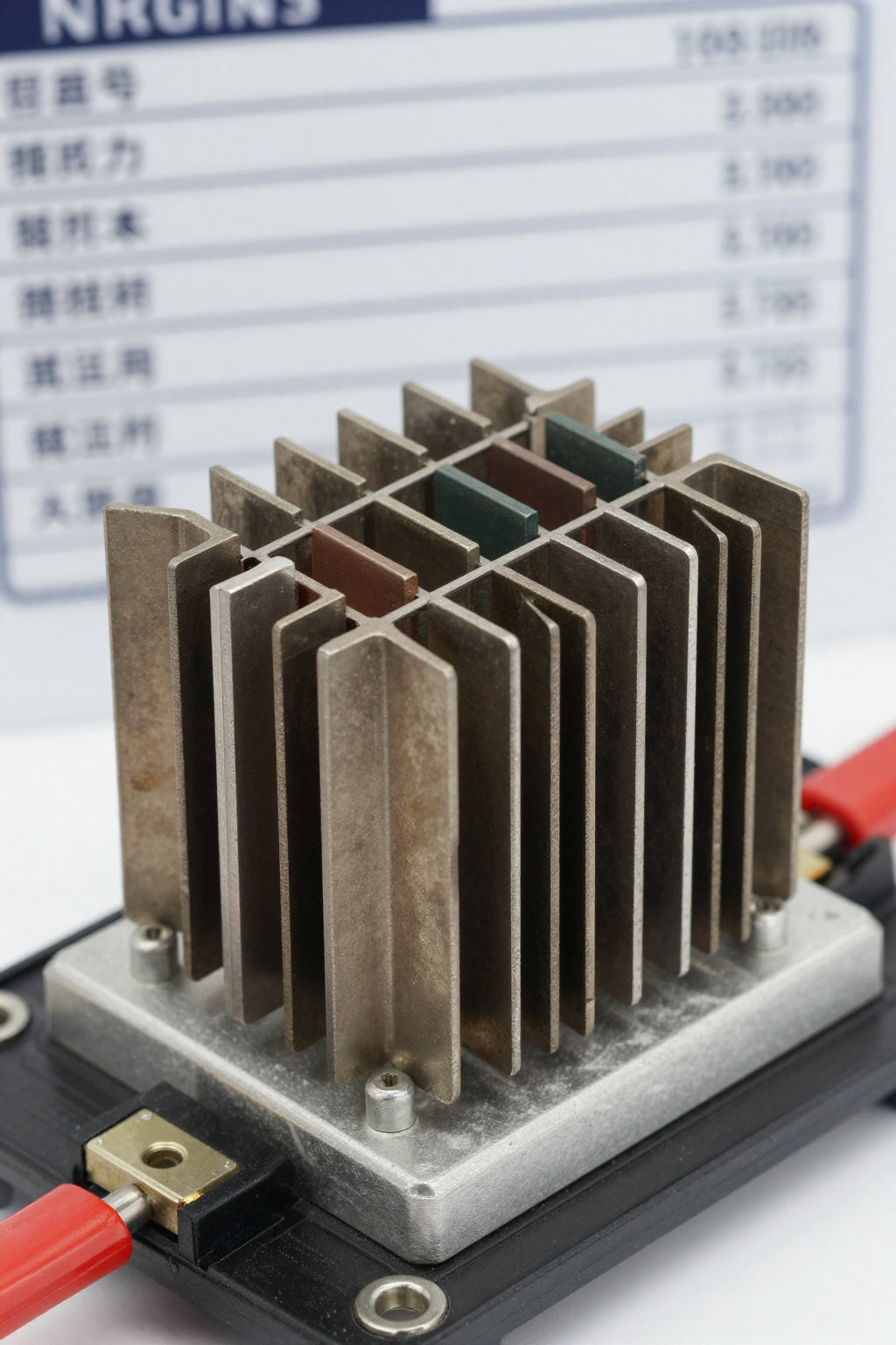
Accurately understanding the model naming convention is the first step in component selection.ULV 60 N 12 J FL=1000is not just a random string of characters; it is a complete technical language that includes information about the series, power rating, resistance value, precision, and package type.
Step-by-Step Breakdown of the Model Naming Convention
This model can be divided into five key segments:ULVRepresents the series platform, typically referring to high-power, low-inductance wire-wound or thick-film structures;60Indicates a rated power of 60W;12Indicates a nominal resistance value of 12Ω;JDenotes an accuracy grade of ±5%;FL=1000This refers to the package and lead code, where FL often corresponds to a specific lead form and mounting dimensions. Each segment directly affects installation compatibility and electrical performance, so it must not be overlooked during verification.
Product Positioning and Typical Application Scenarios
The 60W 12Ω combination is designed for medium-power, low-resistance energy absorption and current sensing applications. Typical uses include discharge resistors in industrial power supplies, braking circuits in inverters, battery load testing, and current-limiting stages in motor drives. In these scenarios, resistors must continuously handle substantial currents, making power margin and thermal design the primary considerations during selection.
In-depth Analysis of Core Specifications: Breaking Down Key Parameters of the 60W 12Ω Resistor
The numbers on the datasheet only become meaningful when applied to actual operating conditions. Below, we dissect the critical parameters from both electrical and thermal perspectives.
| Parameter Category | Specific Item | Value/Description |
|---|---|---|
| Electrical Parameters | Rated Power | 60W @ 25°C |
| Nominal Resistance Value | 12Ω | |
| Tolerance Grade | J (±5%) | |
| Physical/Thermal | Operating Temperature Range | -55°C ~ +200°C+ |
| Package Code | FL=1000 (Specific Leads) | |
| TCR | Refer to the specific datasheet |
Electrical Parameters
The rated power of 60W serves as the baseline, but the actual allowable power is constrained by the ambient temperature derating curve. A resistance value of 12Ω with ±5% accuracy (Class J) means that at 25°C, the resistance deviation ranges from 11.4Ω to 12.6Ω. The TCR (temperature coefficient of resistance) determines the resistance drift after temperature rise, which is especially critical for current sensing applications. The maximum operating voltage and insulation withstand voltage define the safety boundaries; when selecting components, ensure that the operating voltage does not exceed 80% of the rated value.
Physical and Thermal Parameters
The package and lead configuration represented by FL=1000 directly affect the mounting method and thermal dissipation path. The operating temperature range typically spans from -55°C to above +200°C, but the power handling capability decreases linearly as ambient temperature rises. Thermal resistance parameters determine the temperature rise per unit of power; if the thermal resistance of the mounting baseplate or heatsink is too high, a 60W rated power may only deliver half its intended performance under actual conditions. Therefore, thermal resistance and thermal design considerations must be calculated in tandem with power derating.
Selection Guidelines: How to Choose a 60W 12Ω Resistor Without Running Into Problems
Selection errors often stem not from misreading specifications, but from overlooking the gap between operating conditions and datasheet ratings. The following three dimensions are critical for decision-making.
Power Derating and Thermal Condition Verification
When the ambient temperature exceeds 25°C, the actual allowable power must be derated according to the derating curve. Installation method is equally critical: the presence or absence of a heatsink, baseplate material, and contact thermal resistance all affect the thermal path. It is recommended to keep the actual loaded power below 70% of the derated rated value to allow for margins against surges and long-term aging.
Matching Accuracy, TCR, and Pulse/Overload Capability
J-grade ±5% accuracy is suitable for discharge and current-limiting applications with loose resistance value requirements; if used for current sensing, measurement errors caused by TCR must be evaluated. Short-term overload and surge withstand capabilities should refer to the pulse energy curves in the datasheet to avoid exceeding the allowable energy during braking or capacitor charging transients.
Approach to Comparing Alternative Models and Conducting Lateral Comparisons Within a Series
For models in the same series with different resistance values or power ratings, the selection logic should focus on power margin, resistance accuracy, and package compatibility. When comparing, prioritize verifying the derating curve, thermal resistance, and lead dimensions rather than just looking at the rated power figure. If the replacement model has a different package, re-verify the mounting torque and heat dissipation contact area.
Typical Applications and Measured References: Performance of 60W 12Ω Under Real Operating Conditions
There is often a gap between laboratory data and actual field performance due to heat dissipation and wiring details. The following two types of scenarios offer valuable lessons.
Key Points for Selection Verification in Braking and Discharge Circuits
In braking energy absorption scenarios, calculate the energy per brake event and the cycle frequency. Rapid temperature rise usually results from insufficient thermal mass of the heat sink baseplate or excessive contact thermal resistance. It is recommended to measure the full-load temperature rise and observe resistance drift after multiple cycles to ensure it remains within the allowable accuracy range over long-term service life.
Precautions for Current Sensing and Load Simulation Scenarios
When low-value resistors are used for current sensing, wiring methods and parasitic parameters can introduce measurement errors. Using a four-wire Kelvin connection can significantly reduce the impact of lead resistance. In load simulation scenarios, attention should be paid to heat accumulation under continuous full-load conditions to prevent actual power from exceeding limits due to rising ambient temperatures.
Procurement and Usage Action Checklist: From Datasheet to Implementation
Turning a datasheet into reliable components requires an actionable checklist.
Datasheet Checklist
Essential items to check include: rated power and derating curve, resistance value and tolerance, TCR, maximum operating voltage, insulation withstand voltage, package size and lead configuration, and mounting torque requirements. Items that are easily overlooked are the test conditions for the derating curve and heatsink installation instructions, as these two directly determine the actual current-carrying capacity.
Recommendations for Incoming Inspection and Board-Level Verification
During the incoming material stage, it is recommended to randomly inspect resistance values and physical dimensions, and perform power testing when necessary. After mounting, first conduct a temperature rise test and record the stable temperature under full load; then carry out long-term reliability observation, monitoring resistance drift and lead solder joint conditions. If the temperature rise exceeds the value recommended in the datasheet, prioritize improving heat dissipation conditions rather than simply derating the component.
Key Summary
- ULV 60 N 12 J FL=1000The model code includes series information, 60W power rating, 12Ω resistance value, ±5% tolerance, and FL=1000 package details.
- The 60W rated power must be verified against ambient temperature derating curves and heat dissipation conditions; the actual load is recommended not to exceed 70% of the derated value.
- The core of selection lies in matching thermal resistance with the heat dissipation path; J-grade precision is suitable for discharge and current limiting applications, while current sensing requires additional assessment of TCR effects.
- Procurement verification should cover derating curves, installation torque, and package dimensions; post-mounting, thermal design must be validated through temperature rise testing.
Frequently Asked Questions
ULV 60 N 12 J FL=1000Can the resistor operate at full load of 60W at any temperature?
No. 60W is the rated value at the reference ambient temperature; when the ambient temperature rises, it must be adjusted according to the derating curve. If no heatsink is used or if the baseplate thermal resistance is high during actual installation, the allowable power will decrease further. It is recommended to base decisions on measured temperature rise and keep the operating power below 70% of the derated value.
How do a 12Ω resistance value and ±5% tolerance affect applications for this resistor?
A low resistance of 12Ω is suitable for discharge and current-limiting applications with higher currents, and a ±5% tolerance means the resistance value varies between 11.4Ω and 12.6Ω. For current-sensing applications, measurement error after temperature rise must be evaluated in conjunction with TCR; for discharge and braking scenarios, this accuracy is generally sufficient.
What should be considered when selecting the FL=1000 package code?
FL=1000 denotes a specific package and lead configuration, directly affecting mounting dimensions, wiring methods, and thermal contact area. When replacing or designing anew, it is essential to verify lead spacing, mounting hole locations, and torque requirements; package incompatibility can alter the thermal path, thereby impacting actual power-handling capability.
How can the long-term reliability of this resistor in a braking circuit be verified?
It is recommended to first conduct a full-load temperature rise test, recording the steady-state temperature and resistance drift; then simulate the actual braking cycle frequency to observe the cumulative temperature rise and resistance changes after multiple cycles. If the temperature rise approaches the derating limit, improve heat dissipation or reduce the energy per cycle to ensure stable parameters over long-term operation.


