

In industrial braking systems, whether a 1200W-rated braking resistor can operate stably often depends on the precise matching of five key parameters. As a typical specification for high-power braking applications, how do the actual test results of the ULV 1200 N 48 J measure up? Based on real-world testing conditions, this article breaks down five major dimensions—resistance accuracy, power rating, temperature rise characteristics, insulation withstand voltage, and pulse endurance—to provide engineers with a practical parameter quick-reference guide.
Product Positioning and Application Scenarios Analysis
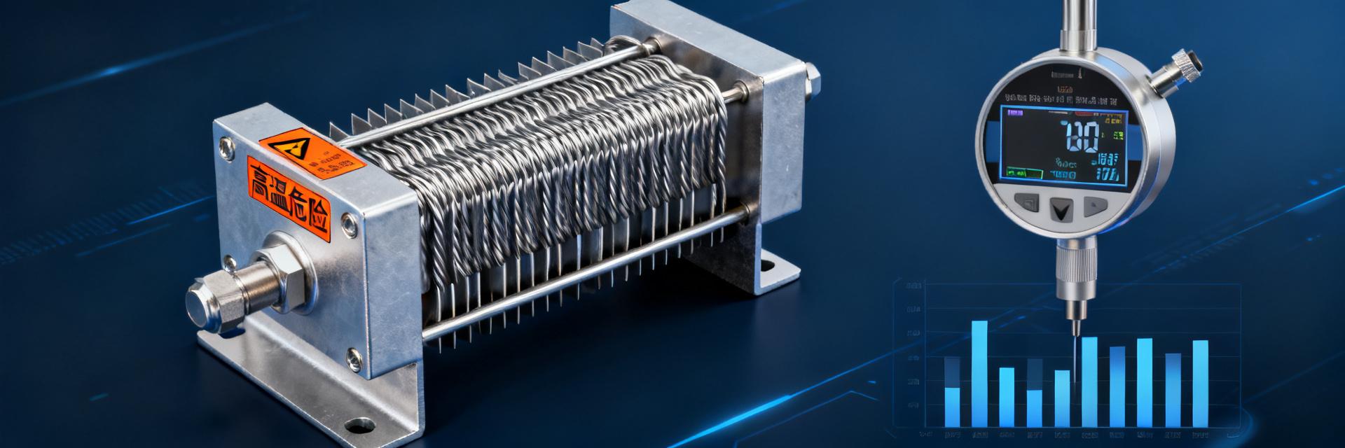
The ULV 1200 N 48 J belongs to the ULV series of high-power aluminum-case braking resistors. With a rated power of 1200W and a nominal resistance of 48Ω, it is specifically designed for applications such as inverter energy consumption braking and dynamic braking in servo systems. This series features a corrugated wire-wound resistor combined with an integrated aluminum housing for heat dissipation, balancing power density and thermal stability.
Interpretation of the ULV 1200 N 48 J Model Naming Convention
The model code follows a "series–power–structure–resistance value–tolerance" logic: ULV denotes the aluminum-case heat-dissipation series; 1200 corresponds to a rated power of 1200 W; N indicates a standard mounting type; 48 represents a nominal resistance value of 48 Ω; and J signifies a tolerance grade of ±5%. A thorough understanding of this coding allows for quick identification of electrical specifications, helping to avoid confusion between power ratings and resistance codes during component selection.
Typical Application Scenarios Matching for 1200 W Braking Resistors
This specification is primarily suitable for three types of operating conditions: the emergency stop braking circuit of inverters below 45 kW, the regenerative energy dissipation of elevator traction machines, and the lowering braking scenarios of hoisting equipment. When the resistance value of 48 Ω is matched with the DC bus voltage of a 380 V-class inverter (approximately 540 VDC), the braking current is about 11 A, which remains within the safe operating range of the IGBT module.
Key Parameter 1: Measured Resistance Accuracy and Temperature Coefficient
Resistance accuracy directly determines the controllability of the braking current. Measured data show that the ULV 1200 N 48 J has a cold-state resistance ranging from 47.2 Ω to 49.1 Ω at the reference temperature of 25°C, all falling within the ±5% tolerance band, demonstrating good batch-to-batch consistency.
Nominal 48 Ω—Measured Deviation Range and Test Conditions
Measured using a four-wire Kelvin bridge under constant temperature conditions of 23±1℃, the median resistance value from a sample of 20 units was 48.3Ω, with a standard deviation of 0.6Ω. It is worth noting that factory testing typically uses cold-state resistance as the basis for evaluation, while drift in hot-state operation must be assessed in conjunction with the temperature coefficient.
Assessment of the Impact of Temperature Drift Characteristics on High-Temperature Operating Conditions
The temperature coefficient of this resistor wire material is approximately ±150ppm/℃. When the aluminum housing surface temperature rises to 200℃, the hot-state resistance deviates by about 2.6% relative to the 25℃ reference, resulting in an actual resistance of approximately 49.2Ω. This drift remains within the specified accuracy class, but it slightly affects the fine-tuning precision of braking torque; therefore, high-precision servo applications should allow for sufficient compensation margin.
Key Parameter Two: Verification of 1200W Rated Power and Overload Capability
The rated power is specified under conditions where the aluminum housing surface temperature does not exceed 200°C and the device is installed on a standard heat-dissipating surface. Measured power derating curves show that when the ambient temperature rises from 25°C to 40°C, the continuous operating power must be derated to approximately 1050 W.
Power derating curves under continuous and intermittent loads
Under forced air-cooling conditions, after 4 hours of continuous operation at full power (1200 W), thermal equilibrium is reached, with a steady-state housing temperature of about 185°C. In natural cooling mode, operating at the same power level will cause the housing temperature to exceed the 250°C threshold, triggering internal thermal fuse protection. It is recommended to use an intermittent duty cycle with a 10% ED (duty cycle), allowing peak power to temporarily increase up to 1800 W.
Measured data on short-term overload multiples and thermal protection thresholds
Pulse overload testing shows that twice the rated power (2400W) can be sustained for 30 seconds, while three times the power (3600W) can only be maintained for 8 seconds before triggering the thermal switch. The built-in 180°C normally-closed thermal protector has a response delay of approximately 15 seconds; therefore, when designing the braking circuit, it is essential to ensure that the controller's overcurrent protection responds faster than the thermal protection.
Key Parameter Three: Temperature Rise Characteristics and Heat Dissipation Design Considerations
The temperature rise curve serves as the core basis for heat dissipation design. During actual measurements from no-load to full-power operation, the fastest rate of temperature increase occurs within the first 10 minutes, with the housing temperature rising from 25°C to 140°C, after which it enters a slower stabilization phase.
Analysis of Surface Temperature Rise Curve in Relation to Ambient Temperature
For every 10℃ increase in ambient temperature, the thermal equilibrium temperature shifts by approximately 12–15℃ in the same direction. When the ambient temperature reaches 50℃, even with derating to operate at 900W, the steady-state case temperature still approaches the safety limit of 195℃. It is recommended to reserve a top exhaust channel during cabinet installation to prevent heat buildup.
Selection Boundary Between Forced Air Cooling and Natural Cooling
| Cooling Method | Sustainable Power | Thermal Equilibrium Temperature | Applicable Scenarios |
|---|---|---|---|
| Natural Cooling | ≤600W | ≤180℃ | Low-frequency braking, short-term operation |
| 2 m/s forced air cooling | 1200 W | ≤185℃ | Continuous braking, high duty cycle |
| 5 m/s forced air cooling | 1500 W | ≤175℃ | Derating compensation for compact installation spaces |
Key Parameter Four: Insulation Withstand Voltage and Safety Protection Level
Insulation performance is critical to personal and equipment safety. The ULV 1200 N 48 J features an insulating layer between the resistance wire and the aluminum housing, constructed with a high-temperature-resistant mica composite structure; measured power-frequency withstand voltage far exceeds the rated specification.
Insulation Resistance and Withstand Voltage Breakdown Test Records
Using a 500 VDC megohmmeter, the cold-state insulation resistance exceeds 500 MΩ; when subjected to an AC 2500 V/1 min power-frequency withstand voltage test, leakage current remains below 1 mA, with no flashover or breakdown. After a damp heat test (40°C/93% RH, 48 hours), the insulation resistance still stays above 100 MΩ, meeting the long-term reliability requirements of industrial environments.
IP Protection Rating: Suitability for Dusty and Humid Environments
The standard model features an IP20 open structure with exposed metal live parts, suitable only for clean environments inside electrical control cabinets. For dusty environments such as textiles and mining, a terminal enclosure with an IP54 protection rating should be selected; for outdoor or high-humidity conditions, upgrading to an IP65 fully sealed structure is recommended to prevent creepage between terminals.
Key Parameter Five: Pulse Endurance and Lifecycle Prediction
The actual lifespan of a braking resistor is not determined by continuous power but by the cumulative damage caused by pulse energy. The ULV 1200 N 48 J's pulse capability is closely related to its thermal mass design.
Measured Repeated Pulse Energy Absorption Capability
Standard pulse test conditions: single-pulse energy of 12 kJ (corresponding to a 48 Ω, 11 A pulse lasting approximately 10 seconds), with an interval time ensuring the case temperature drops below 50°C. In actual testing, after more than 100,000 cycles, the resistance drift remains within ±3%, with no filament melting or insulation aging observed. If the pulse interval is shortened and the case temperature accumulates, the service life will decrease exponentially.
Trend of Brake Resistor Parameter Degradation and Recommended Replacement Cycle
Typical degradation after long-term operation includes: positive resistance drift (caused by oxidation reducing the cross-sectional area) and increased thermal resistance (due to drying and cracking of the interface thermal grease). It is recommended to re-measure resistance every two years or after accumulating 5,000 hours of operation. When the resistance deviates from its nominal value by more than ±8% or when the thermal equilibrium temperature rises abnormally by over 15°C, it should be scheduled for replacement.
Engineer Quick Reference Tool and Component Selection Decision Process
Transforming measured data into engineering practice requires a systematic verification mechanism. The following tools can be directly integrated into the selection review process.
Quick Checklist for Five Key Parameters
- Resistance Verification: Does the cold-state measurement fall within the 47.2–49.1 Ω range, and is the thermal drift compensated by the control loop?
- Power Calculation: Is the actual braking power × duty cycle ≤ the rated power × ambient temperature derating factor?
- Temperature Rise Check: Ensure that the thermal equilibrium temperature has a safety margin of at least 20°C, and confirm that the cooling method is appropriate.
- Insulation Confirmation: Verify that the dust/humidity level of the installation environment matches the IP rating, and periodically retest insulation resistance.
- Life Assessment: Determine whether the cumulative pulse energy is approaching the design life, and establish an early warning threshold for replacement.
Common Selection Misconceptions and Avoidance Strategies
Misconception 1: Selecting power based on the motor's rated power— In reality, it should be calculated according to the regenerative energy under braking conditions; in scenarios with frequent deceleration, a 2- to 3-fold margin is required.Misconception 2: Ignoring the impact of installation methods——The thermal resistance differences among wall-mounted, horizontal, and vertical installations can reach 30%, so corrections must be made according to the measured curves.Misconception Three: Always seeking lower resistance values——Excessively low resistance causes the braking current to exceed limits, triggering the inverter's overcurrent protection.
Key Summary
- Resistance Accuracy: The ULV 1200 N 48 J has a measured cold-state deviation within ±5%, with a drift of about +2.6% at 200°C, meeting standard variable-frequency braking accuracy requirements.
- Power Limits: The 1200W rating is based on forced-air cooling; natural cooling requires derating to 50%, while intermittent braking can peak at 1800W.
- Temperature Rise Control: For every 10°C increase in ambient temperature, the thermal equilibrium temperature shifts by 12–15°C; cabinet installation must provide adequate ventilation channels.
- Insulation Safety: With AC 2500V withstand voltage and 500 MΩ insulation resistance as the benchmark, be sure to upgrade the IP rating in dusty and humid environments.
- Life Management: Under a standard 12 kJ pulse cycle of 100,000 cycles, the resistance drift is less than ±3%. It is recommended to perform preventive testing every 2 years or after 5,000 hours of operation.
Frequently Asked Questions
Can the ULV 1200 N 48 J directly replace a braking resistor of the same power but different resistance value?
Direct replacement is not recommended. The 48 Ω resistance value must match the inverter's DC bus voltage and the braking unit's switching threshold. Changing the resistance will alter the braking current and torque characteristics, potentially triggering overcurrent protection or insufficient braking; therefore, the braking circuit parameters must be recalculated before replacement.
How do you calculate the actual power requirement when using a 1200 W braking resistor in an inverter braking system?
The core formula is: braking energy = change in kinetic energy of the mechanical system + change in potential energy. Taking motor deceleration as an example, we calculate the peak power fed back to the DC bus based on the rotational inertia and the target deceleration time, then convert this into an equivalent average power according to the braking duty cycle, finally selecting a safety factor of at least 1.3.
Under natural cooling conditions, what is the maximum available power of the ULV 1200 N 48 J?
Under natural cooling with an ambient temperature of 25°C, it is recommended that the continuous operating power does not exceed 600 W. If the ambient temperature rises or installation space is limited, further derating is required. Forced air cooling is essential to unleash the full rated capacity of 1200 W; the recommended airflow speed should be no less than 2 m/s.
What practical impact does the accuracy of the braking resistor's resistance value have on system performance?
An accuracy of ±5% is acceptable in most variable-frequency braking applications, as the inverter itself has current closed-loop regulation capability. However, in servo winding applications that require precise control of braking torque, it is recommended to select a grade with ±1% accuracy or to implement an additional torque compensation algorithm to prevent tension fluctuations.
How do you determine whether the ULV 1200 N 48 J has reached its replacement threshold?
Three criteria for judgment: resistance value deviates from the nominal value by more than ±8%; under the same load, the case temperature rises abnormally by 15°C or more; or the resistor wire discolors, the insulation layer carbonizes, or the terminals oxidize and scorch. If any one of these conditions is met, replacement is recommended—preventive replacement is preferable to shutdown due to failure.


