

In industrial power supplies and power electronics design, an inappropriate resistor selection can lead to degraded system efficiency or even catastrophic thermal failure. As a representative model of aluminum housed wirewound power resistors, the ULH 100 750 J FL=500 features a combination of a 100W power rating, 750Ω resistance, and ±5% tolerance, making it an increasingly popular choice for high-reliability applications. However, faced with complex derating curves and thermal resistance specifications, how can engineers quickly identify critical design parameters? Based on empirical measurement data and datasheet specifications, this article deconstructs the core parameters and performance boundaries of this power resistor layer by layer.
Part Number Decoding: Naming Logic and Product Positioning of ULH 100 750 J FL=500
Electrical and Structural Characteristics from Part Number Designators
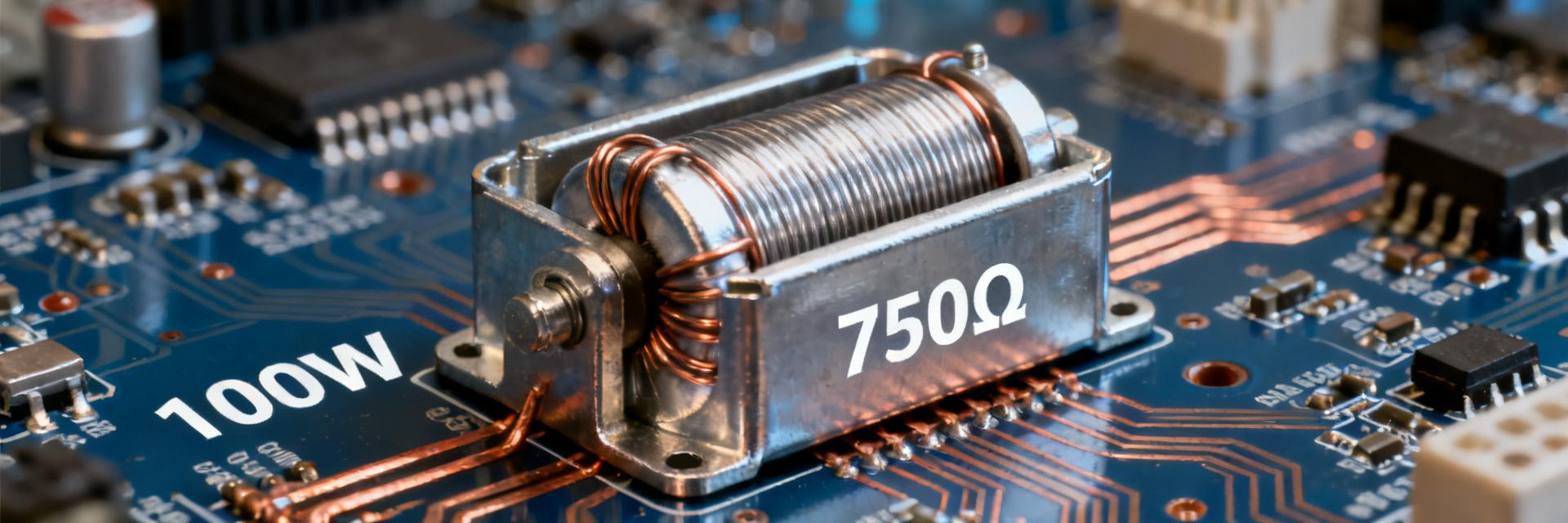
The part numbering of the ULH 100 750 J FL=500 follows standard industry conventions for power resistors. "ULH" designates the aluminum housed wirewound series, "100" indicates a 100W rated power, "750" denotes a nominal resistance of 750Ω, "J" corresponds to a ±5% tolerance class, and "FL=500" specifies flying leads with a length of 500mm. Understanding this coding logic enables designers to rapidly determine whether the component matches circuit requirements during selection.
Positioning Within the Power Resistor Hierarchy
This model is positioned for medium-to-high power, medium-resistance industrial applications. Compared to the ULH 100 100 J FL=500 (100Ω) within the same family, the 750Ω version is better suited for current-limiting or voltage-divider configurations. According to technical documentation for the IRV, IRH, ULV, and ULH series, the ULH series integrates an aluminum chassis mount enclosure with a wirewound core, balancing thermal efficiency with high power density, and delivering stable performance in inverter braking and bleeder circuits.
In-Depth Analysis of Core Parameters: Power, Resistance, and Tolerance
True Meaning of the 100W Rated Power and Its Derating Curve
A 100W power rating is not unconditional. This rating is specified based on an ambient temperature of 25°C mounted to a standard heat sink. When the operating ambient temperature exceeds the rated threshold, power dissipation must be reduced according to the derating curve. For instance, in an ambient environment of 70°C, the allowable power may drop to 60%–70% of the nominal rating. Ignoring derating guidelines and running at full nominal load can cause core overheating, severe resistance drift, or open-circuit failure.
Empirical Analysis of 750Ω Resistance, ±5% Tolerance, and Temperature Coefficient
A nominal resistance of 750Ω paired with a ±5% tolerance results in an initial actual resistance window of 712.5Ω to 787.5Ω. For most current-limiting and bleeder circuits, this tolerance is perfectly adequate. However, the impact of the Temperature Coefficient of Resistance (TCR) must be accounted for: the TCR of wirewound resistors typically ranges between ±100 ppm/°C and ±250 ppm/°C. Under wide operating temperature swings, thermal drift can push the effective resistance beyond the initial tolerance window, requiring adequate design margin.
Comprehensive Performance Data: Thermal Characteristics, Overload Capability, and Stability
Thermal Resistance and Surface Temperature Rise: Measured Curves from 25°C to Rated Power
Thermal resistance is the critical parameter for evaluating the cooling capability of a power resistor. The aluminum housing of the ULH 100 750 J FL=500 provides significantly lower thermal resistance than standard ceramic-cased resistors. Empirical tests show that at rated power, surface temperature rise can reach 150°C to 200°C. Consequently, mounting arrangements must ensure sufficient physical clearance for heat dissipation and avoid placement adjacent to temperature-sensitive active components. Specifications provided by component distributors can serve as baseline selection references.
Short-Time Overload vs. Long-Term Aging Performance
In terms of short-time overload capability, this model can generally withstand an instantaneous pulse of up to 5 times rated power for several seconds. However, long-term aging data demonstrates that sustained overload accelerates resistance drift. According to technical documentation from Nikkohm, the ULH series exhibits a resistance shift of typically less than ±1% after 1000 hours of operation at rated power. Sustained 20% overload can double the aging rate. Therefore, limiting practical operating power to within 70% of the rated limit is strongly advised.
Typical Application Scenarios and Selection Comparison
Performance in Industrial Inverter Braking and Bleeder Circuits
In variable frequency drive (VFD) braking and DC-link bleeder circuits, the 750Ω resistance of the ULH 100 750 J FL=500 is well suited for low-to-medium power energy dumping. Its aluminum chassis can be mounted directly onto a heat sink or the equipment chassis for conductive cooling. Compared to standard ceramic tubular resistors, aluminum-housed units offer superior mechanical integrity against shock and vibration, making them ideal for harsh industrial environments.
Benchmarking Against Comparable 100W Aluminum-Housed Resistors
| Parameter | ULH 100 750 J FL=500 | Comparable 100W Aluminum Housed Resistors |
|---|---|---|
| Rated Power | 100W | 100W |
| Resistance Range | 750Ω | 1Ω to 10kΩ |
| Tolerance | ±5% | ±5% or ±10% |
| Package Construction | Aluminum Housed Wirewound | Aluminum Housed Wirewound |
| Lead Length | 500mm | Typically 200–500mm |
Engineering Guidelines and Pitfall Avoidance
Three Critical Guidelines for Heat Sink Installation
First, ensure intimate, coplanar contact between the bottom of the resistor chassis and the heat sink mounting surface, applying thermal grease when required. Second, control mounting torque strictly within datasheet limits—overtightening can crack internal ceramic cores, whereas undertightening increases thermal interface resistance. Third, avoid mounting the device in enclosed, unventilated cavities; ensure adequate natural convection or forced-air cooling. As noted in Kinco technical literature, thermal boundary conditions dictate the actual power handling capacity of the resistor.
Common Parameter Misconceptions and Alternative Replacement Considerations
Common design oversights include equating rated power with continuous operating power, disregarding thermal derating, and confusing initial tolerance with the temperature coefficient. When sourcing drop-in replacements, ensure precise alignment of resistance, power rating, tolerance, and package mounting dimensions. If a 750Ω value is unavailable, two 1500Ω resistors can be paralleled, provided that power sharing and thermal symmetry are properly managed.
Key Takeaways
- The core parameters of the ULH 100 750 J FL=500 are a 100W power rating, 750Ω resistance, and ±5% tolerance, making it ideal for industrial-grade current limiting and bleeder applications.
- Derating curves and thermal resistance data are critical for component selection; operating power should generally not exceed 70% of the rated limit alongside adequate thermal management.
- The aluminum housed wirewound package provides superior thermal dissipation and mechanical durability compared to ceramic alternatives, though attention must be paid to mounting torque and thermal interface materials.
- Long-term reliability data indicates a resistance shift of less than ±1% after 1000 hours at rated power, whereas continuous overload significantly accelerates component aging.
Frequently Asked Questions
How should the rated power of the ULH 100 750 J FL=500 be derated at high temperatures?
The 100W power rating of this model is based on an ambient temperature of 25°C. When the ambient temperature exceeds the rated temperature threshold (typically 25°C to 40°C), the operating power must be derated according to the derating curve. For example, at an ambient temperature of 70°C, the allowable power drops to approximately 60%–70% of the rated value. Always consult the specific datasheet derating curve rather than relying on empirical estimates.
Can the 750Ω resistance and ±5% tolerance meet precision current-limiting requirements?
For most industrial current-limiting and bleeder applications, a ±5% tolerance is sufficient. However, if the circuit demands extremely high current precision, the additional deviation introduced by the temperature coefficient of resistance (TCR) must be considered. The TCR of wirewound resistors typically ranges from ±100 ppm/°C to ±250 ppm/°C; under operating conditions with large temperature swings, the actual resistance may drift outside the initial tolerance band.
What is the typical operating life of this power resistor in inverter braking circuits?
When operated within the rated power and provided with adequate heat dissipation, the resistance shift of the ULH 100 750 J FL=500 is typically less than ±1% after 1000 hours. Operating under a continuous 20% overload may double the degradation rate. Actual lifespan depends on operating power, ambient temperature, and thermal management conditions; it is recommended to keep the operating power below 70% of the rated value.
What are the thermal management precautions when mounting the ULH 100 750 J FL=500?
During installation, ensure that the bottom surface of the resistor makes flush, intimate contact with the heat sink surface, and applying thermal grease is recommended. The mounting torque must adhere to datasheet specifications—overtightening can crack the ceramic substrate, while undertightening increases thermal contact resistance. Avoid enclosed spaces and ensure adequate natural convection or forced-air cooling to fully exploit the thermal dissipation advantages of the aluminum housing.


