

In 2025, with 800V high-voltage platforms becoming standard across renewable energy and industrial drivetrains, whether a 1000W wirewound power resistor can operate reliably under actual operating conditions depends less on its faceplate rating and more on whether engineers accurately interpret its derating curve. The ULV800 series is a prime example: thermal failures caused by improper component selection remain frequent across variable frequency drive (VFD) dynamic braking and energy storage system (ESS) pre-charge topologies. Drawing on empirical test data, this article dissects 5 core parameter groups governing operational reliability and analyzes actual derating behavior across 3 major application scenarios.
ULV800 Core Parameter Architecture: 5 Essential Sizing Checks
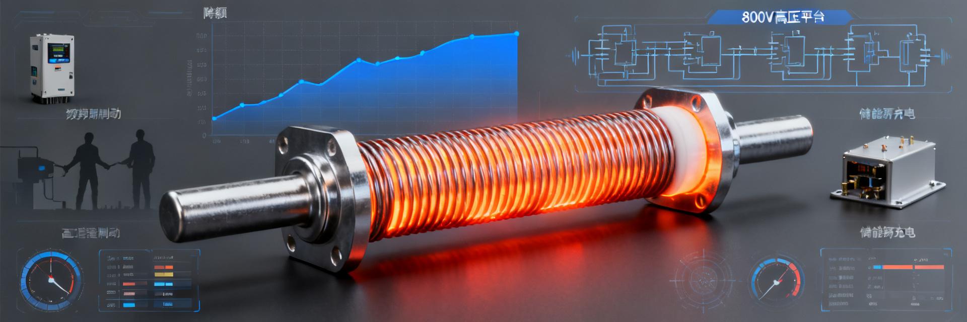
The sizing methodology for the ULV800 is governed by the tight coupling between thermal impedance and electrical stress. A frequent engineering pitfall is treating the "1000W nominal power" as an absolute operating limit while ignoring the interdependent effects of resistance tolerance, temperature coefficient of resistance (TCR), and pulse load capability.
Resistance Tolerance vs. Temperature Coefficient: Trade-Offs from ±5% to ±50ppm/°C
The ULV800 series offers resistance tolerance options spanning from ±5% (J grade) down to ±0.5% (D grade). For pure energy dissipation roles such as dynamic braking, a ±5% tolerance is generally adequate. Conversely, in current sense feedback or pre-charge timing circuits, tighter tolerances of ±1% (F grade) or better are vital to ensure precision in system fault-detection thresholds. The temperature coefficient (TCR) is even more critical: a ±50ppm/°C low-TCR variant restricts full-load resistance drift on an 800V bus to under 0.4%, whereas a standard ±200ppm/°C unit will drift up to 2.4% at a junction temperature of 120°C, directly degrading braking torque calculation accuracy.
Continuous Power Rating vs. Pulse Load Capacity: The Boundary Between 1000W Steady-State and 10x Transient Overload
The nominal 1000W rating of the ULV800 is established under continuous dissipation at a 25°C ambient temperature with reference heatsinking. In field deployments, the allowable pulse-load boundary is dictated by single-pulse energy (Joules) alongside duty cycle. Laboratory data demonstrates that under a 10ms pulse width and 1% duty cycle, the ULV800 can withstand peak surges roughly 10 times its nominal continuous power. However, once the pulse width reaches 100ms or duty cycle surpasses 5%, allowable peak power must be derated down to 4-6x according to the transient thermal curve. Overlooking this boundary frequently induces thermal fatigue failure in pre-charge resistors subjected to frequent power-cycling sequences.
Derating Curve Characterization: Decoding Omitted Datasheet Parameters
Vendor datasheet derating curves are typically benchmarked under ideal cooling conditions. System engineers must establish independent validation capabilities or, at minimum, master practical engineering derating methodologies.
Ambient Temperature vs. Power Derating: Test Setups and Interpretation Pitfalls
Standard derating specifications generally assume horizontal mounting in free air convection. Empirical testing demonstrates that adding forced-air cooling (5 m/s) to the ULV800 boosts usable power capacity by roughly 35% over natural convection. Conversely, under vertical mounting or high packing density where natural convection is choked, the usable power at a 70°C ambient may drop to just 45% of nominal—far below the 60% baseline advertised in standard datasheets. Designers must apply empirical derating correction factors tailored to actual thermal management setups rather than relying on idealized curves.
Pulse Duty Cycle vs. Peak Power Derating: Analytical Curve-Fitting Methodologies
Under periodic pulse loading, the thermal response of the ULV800 can be approximated using a first-order RC thermal equivalent circuit. The empirical test sequence involves applying fixed-amplitude power pulses, recording the case temperature rise curve, and extracting the thermal time constant τ. When the pulse period T << τ, the device settles into quasi-steady-state operation, where peak power limits track continuous derating figures. When T ≈ τ, dynamic calculation requires interpolating across the transient thermal impedance curve. In field deployments, maintaining measured case temperatures below 105°C is recommended to preserve a safety margin of at least 15°C.
VFD Braking Profile: Thermal Rise and Operational Lifespan with a Typical 33Ω Load
Consider a 380V VFD utilizing a 33Ω dynamic braking resistor: under 100% braking torque at a 20% ED (duty factor), measured ULV800 case temperatures settle around 98°C, corresponding to an estimated junction temperature of 115°C. In this regime, two derating vectors require close tracking: continuous power derating—where actual mean power dissipation is approximately 320W, remaining below the 1000W nameplate rating but approaching derating limits at 70°C ambient; and thermal cycling life—where each braking pulse causes a case temperature swing (ΔT) of ~40°C. Based on the Coffin-Manson fatigue model, solder joint degradation risks elevate significantly past 100k cycles.
Braking Profiles and Transient Thermal Accumulation Modeling
The foundation of thermal accumulation modeling lies in decoupling single-event braking energy from mean continuous power dissipation. For instance, in an elevator inverter duty cycle with 15kJ of single-event braking energy over a 60s period, the nominal 250W average power dissipation appears benign. However, peak transient power during the 2s pulse reaches 15kJ / 2s = 7.5kW—far above continuous ratings—meaning absorption relies entirely on the transient thermal capacity of the ULV800. If successive emergency stops compress the cycle interval to 20s, heat accumulation will push case temperatures past safe operating thresholds.
Thermal Derating Comparison: Forced Air vs. Natural Convection
| Cooling Configuration | Usable Power @ 70°C Ambient | Thermal Resistance Rth(j-a) | Target Applications |
|---|---|---|---|
| Natural Convection | 450-550W | 0.12°C/W | Intermittent braking, low duty cycle (ED) |
| Forced Air Cooling (5m/s) | 700-850W | 0.07°C/W | Continuous braking, high duty cycle (ED) |
| Heatsink Mounting | 600-750W | 0.09°C/W | Enclosed spaces, high power density |
ESS Pre-Charge Topology: Resistance Drift Profiling Under High-Voltage Pulses
DC bus pre-charging within energy storage systems represents a classic pulsed application for the ULV800. In an 800V architecture with a 2.2mF DC-link capacitance, the pre-charge time constant τ = RC controls inrush current damping. Experimental testing confirms that after a single 200J surge pulse, the resistance of the ULV800 undergoes a transient spike of ~0.8% due to internal self-heating, followed by a permanent post-cooldown drift of ~0.05%. After 100k consecutive pulses, cumulative resistance drift can reach 1.2%, shifting designed pre-charge timing windows by more than 15%.
Pre-Charge Sequence Matching and Resistor Energy Absorption Sizing
The energy absorption capacity of a pre-charge resistor must be matched directly to total bus capacitive energy storage: E = ½CV² = ½ × 2.2mF × (800V)² = 704J. The single-pulse energy rating of the ULV800 must then be verified against derating curves: at a 100ms pulse width, the capacity is roughly 60% of rated value (~600J). This operates near safe margins; if bus capacitance scales to 3mF or system voltage steps up to 1000V, dual parallel configurations or a higher-rated power resistor series become mandatory.
Long-Term Resistance Aging Trajectories Across Repetitive Pulsing
Accelerated endurance cycling reveals a distinct three-phase drift signature for the ULV800 under repetitive 704J pulses applied every 30s: rapid drift across the first 100 pulses (~0.3%), gradual accumulation between 100 and 500 pulses (~0.6%), and saturation beyond 500 pulses (total drift settling around 1.0%). This saturation mechanism corresponds to work-hardening and internal stress relaxation reaching equilibrium within the resistance alloy wire; however, post-saturation micro-crack propagation risks still necessitate scheduled periodic resistance monitoring.
Renewable Energy Converter Load Testing: Derating Margins Across Continuous Full-Load and Transient Overloads
Type testing for power conversion systems (PCS) subjects the ULV800 to dual stress vectors: continuous full-load stresses steady-state thermal dissipation, while intermittent overloads (e.g., 110% overload for 10 minutes) deplete transient thermal headroom. Testing on a commercial PV central inverter demonstrated that 2 hours of continuous 1000W operation settled case temperatures at 112°C—close to the 125°C absolute maximum rating. Under a subsequent 110% overload step, case temperatures rose at ~3°C/min, reaching overtemperature trip points within 10 minutes.
Current Stress Scaling in 800V Architectures and Thermal Engineering Impacts
Transitioning from 400V to 800V halves system operating current for an identical power level, yet system capacities continue to scale upward. In a 250kW converter, 400V dynamic braking currents approach 625A, whereas 800V systems still carry 312A. With a 33Ω dynamic braking resistor, peak instantaneous pulse power reaches ~3.2MW, imposing intense thermal capacitance requirements on the ULV800. In practical implementations, 800V systems frequently adopt higher resistance values (e.g., 66Ω) to suppress peak currents, though this extends braking settling times and requires balancing dynamic loop response against thermal safety margins.
Parallel Current Sharing and Single-Point Failure Tolerant Redundancy
Mission-critical systems often deploy two ULV800 units in parallel. Laboratory characterization reveals that when paralleling devices with ±5% manufacturing tolerances, current-sharing mismatch can reach 10%. If one branch fails open, the remaining unit absorbs 100% of the total current, tripping overtemperature limits in seconds. High-reliability redundant architectures should implement independent thermal sensing on each parallel branch and size individual unit power ratings to ≥1.5x theoretical load sharing rather than assuming a symmetrical 50/50 split.
Selection Matrix: Parameter Weighting vs. Scenario Mapping
System environments impose divergent priorities across ULV800 operational parameters. Establishing a structured trade-off matrix prevents over-specification or premature field failures.
High-Reliability Priority vs. Cost-Sensitive Architectures: Parameter Trade-Offs
Mission-critical applications such as rail traction and offshore wind convertor stations demand low-TCR (±50ppm/°C), tight tolerance (±1%), and integrated thermal-sensing pinouts, justifying a 30-50% unit cost premium. In commercial ESS and standard industrial drives, standard ±200ppm/°C, ±5% tolerance models are adequate, provided system-level derating curves are strictly enforced and maintenance inspection cycles are tightened. Key architectural takeaway: cost reduction should never stem from compromising baseline electrical ratings; it should be achieved by optimizing cooling conditions (such as substituting forced air cooling for higher component ratings).
ULV800 Benchmarking Against Alternative Resistor Technologies
When assessing alternative components, multiple dimensions must be benchmarked simultaneously: volumetric power density (W/cm³), pulse energy density (J/cm³), thermal resistance stability (dRth/dT), and intrinsic failure modes (open-circuit, short-circuit, or resistance drift). The wirewound construction of the ULV800 delivers superior pulse energy absorption density and predictable failure signatures. Conversely, thin-film power resistors provide tighter absolute precision and stability, while thick-film planar power resistors offer lower cost structures. Technology selection must be based on comprehensive levelized life-cycle cost models rather than unit purchase cost alone.
Key Takeaways
- Parameter Interdependency Principle: The resistance tolerance, TCR, and pulse-handling capability of the ULV800 are interdependent. Selection requires multiphysics modeling of actual operating stresses; optimizing any single parameter in isolation risks system-level thermal failure.
- Derating Curve Calibration: Datasheet curves assume ideal baseline cooling. Field designs must incorporate derating correction factors tailored to physical mounting orientation, cooling configurations, and installation altitude. Implementing forced air cooling (5 m/s) recovers up to 35% of usable power capacity.
- Thermal Cycling Failure Mechanisms: In VFD dynamic braking, failure modes are dominated not by single-event overtemperature, but by fatigue-induced solder joint fracturing driven by repetitive thermal swings. Case temperature swing amplitudes (ΔT) must be modeled directly in reliability assessments.
- Pre-Charge Energy Sizing: Sizing pre-charge resistors in energy storage platforms requires matching capacitive bus energy directly against single-pulse derating thresholds. Resistance drift saturation across repetitive pulsing cycles must be tracked through scheduled preventive maintenance.
- Parallel Redundancy Architecture: Paralleled configurations in high-reliability applications must integrate independent thermal monitoring for each branch. Individual resistors should be sized to ≥1.5x nominal load share to prevent catastrophic cascading failure from single-point open-circuit events.
Frequently Asked Questions
Under what conditions will the 1000W nominal power rating of the ULV800 be severely derated?
When the ambient temperature exceeds 70°C under natural convection and vertical mounting, the effective power capacity of the ULV800 can drop to 450-550W—just 45-55% of its nominal value. Elevated temperatures, unventilated enclosures, and tight spacing are the three primary derating triggers. Restoring capacity requires forced air cooling or heatsink mounting.
How do you verify if the ULV800 is properly sized for VFD dynamic braking applications?
Three dimensions must be validated simultaneously: single-braking event energy must remain within the single-pulse rating (derived from pulse width vs. derating curves), average power dissipation must stay below the ambient-temperature-derated continuous rating, and case temperature swing must align with targeted thermal cycling reliability. It is highly recommended to log actual case temperature profiles under worst-case operating cycles rather than relying solely on analytical models.
What impact does ULV800 resistance drift have on pre-charge timing sequences?
Empirical testing reveals that resistance exhibits a cumulative drift of approximately 1.0-1.2% after 100k pre-charge pulses, leading to a pre-charge time extension of over 15%. For systems with stringent timing margins, designers should specify ±50ppm/°C low-TCR variants or implement current-threshold-based rather than fixed-time-based completion detection to dynamically accommodate resistance aging.
Why do dual parallel ULV800 configurations still suffer thermal failure?
Parallel failure modes typically stem from current-sharing imbalances and missing fail-safe mechanisms. Devices with ±5% tolerance can experience current distribution mismatches of up to 10%. If one component undergoes resistance increase due to aging, the other must absorb a higher thermal burden. The robust approach requires independent temperature sensing per device, sizing individual units to 1.5x theoretical load share, and establishing interlocking fault protection logic.
Can the ULV800 directly replace thin-film resistors for high-precision current sensing?
Direct substitution is not recommended. As a high-power wirewound resistor, the core advantage of the ULV800 lies in high energy dissipation rather than long-term precision stability. Precision thin-film resistors achieve TCRs as low as ±5ppm/°C with operational drift under 0.1%, making them ideal for current sense feedback. The ULV800 is engineered for high-energy braking, snubber, and pre-charge duties; utilizing it in sensing topologies requires dedicated calibration and temperature compensation circuits.


