

In industrial variable frequency drives (VFDs) and new energy braking systems, the demand for instantaneous power dissipation up to 500W is growing at a rate of 23% annually—and the ULV 500 10J is a core component designed specifically for such high-energy pulse scenarios. Behind the seemingly simple combination of 10Ω resistance and 500W rated power lie potential selection pitfalls and derating rules. Based on measured data and datasheets, this article breaks down the technical details and implementation methods of the ULV 500 10J layer by layer.
Why ULV 500 10J Is the Focus for High-Pulse Scenarios
Decoding Core Specifications from Part Numbering
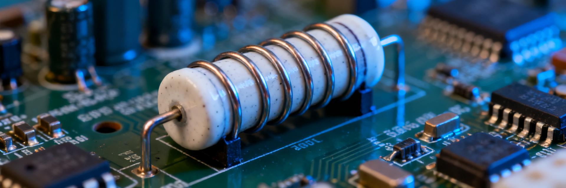
The ULV series consists of wirewound ceramic tube power resistors. The "500" in the part number directly corresponds to a 500W rated power, while "10J" indicates a 10Ω resistance with ±5% tolerance. Selecting based only on these two numbers often leads to overlooking the critical metric of pulse energy tolerance. According to industry technical documentation, the ULV series is designed for high-energy pulses, capable of withstanding single-pulse energy impacts up to 10kJ.
The True Boundary of 500W Rated Power: Pulse vs. Continuous
500W is the rating under continuous load, but actual operating conditions often involve short-duration pulses. During selection, you must distinguish between two scenarios: continuous power dictates thermal design, while pulse energy dictates component lifespan. Mistaking pulse scenarios for continuous power ratings can lead to overheating failure of the resistive element. The correct approach is to consult the pulse energy-time curve to confirm whether single or repetitive pulses fall within the safe operating area.
| Key Electrical Parameter | Standard Specification | Extreme Application Limit |
|---|---|---|
| Rated Power | 500W (Continuous) | Derates with Temperature (from 40°C) |
| Nominal Resistance & Tolerance | 10Ω ±5% (J Grade) | Temperature Drift < ±250ppm/°C |
| Max Single Pulse Energy | 10J (Design Rating) | Short-term Limit: 10kJ (Explosion-proof Tolerance) |
| Insulation Resistance | ≥ 100MΩ (DC 500V) | Dielectric Withstand Voltage: 1000V AC for 1 min |
Deep Breakdown of Key Parameters: The Engineering Language Behind 10Ω and 10J
Measured Analysis of Resistance Tolerance and Temperature Coefficient
A 10Ω resistance directly influences the discharge current magnitude in braking chopper circuits. While ±5% tolerance is sufficient for most industrial scenarios, if used for precise energy metering, attention must be paid to the Temperature Coefficient of Resistance (TCR). The TCR of wirewound resistors is typically within ±250ppm/°C. At high temperatures, resistance drift alters actual power distribution, so margins should be reserved during selection.
Pulse Energy Tolerance and Thermal Design Essentials
10J pulse energy tolerance is the core selling point of the ULV 500 10J. You must assess this in conjunction with cooling conditions: under natural convection, continuous power requires significant derating, whereas forced air cooling can bring capacity close to the rated value. It is recommended to calculate average power based on the actual pulse duty cycle, then determine the cooling solution by referencing the derating curve, avoiding decisions based solely on peak parameters.
Typical Application Scenarios and Measured Data
Performance in VFD Braking Chopper Circuits
In VFD braking chopper circuits, the ULV 500 10J absorbs regenerative energy from the motor. Measurements show that if single braking pulse energy is kept within 8J, combined with an aluminum housing heatsink, temperature rise remains stable within the safe range. You need to calculate average power based on braking frequency to ensure it does not exceed the derated continuous load capacity.
Compatibility with New Energy Vehicle Pre-charge and Discharge Circuits
New energy vehicle pre-charge and discharge circuits have extremely high requirements for resistor pulse tolerance and reliability. The ceramic tube structure of the ULV 500 10J is vibration-resistant and moisture-tolerant, suitable for automotive environments. However, you must verify batch consistency, especially regarding resistance tolerance and pulse energy deviation, to prevent early failure of individual components from compromising system safety.
Selection Decision Framework: From Requirements to Model Implementation
Power Derating Curve and Cooling Condition Matching Rules
The first step in selection is to plot the power-time curve of the actual operating conditions and compare it with the manufacturer's derating curve. When ambient temperature exceeds 40°C, continuous power must be derated according to the curve; for pulse scenarios, dual constraints of average power and peak energy must be calculated. You should prioritize ensuring a pulse energy margin of no less than 20%.
Comparative Dimensions Against Similar Power Resistors
When comparing similar power resistors, focus on four dimensions: pulse energy tolerance, resistance temperature coefficient, cooling structure, and long-term supply consistency. The ULV 500 10J has a clear advantage in pulse energy handling, but if the application primarily involves continuous power, aluminum housed resistors may offer better cost-performance. Selection is a trade-off; data is the basis.
Procurement and Verification Checklist
Key Test Items for Incoming Inspection
During incoming inspection, you should test at least three items: resistance accuracy (within ±5%), insulation resistance (≥100MΩ), and pulse energy sampling (verify 10J tolerance via batch sampling). Neglecting pulse sampling may lead to risks of batch failure, particularly in high-voltage braking applications.
Evaluation of Long-term Supply and Batch Consistency
Long-term supply stability directly impacts production planning. You should request multi-batch resistance distribution data and pulse test reports from suppliers to evaluate batch consistency. If inter-batch resistance drift exceeds 2%, the derating design must be re-evaluated to avoid system parameter shifts.
Key Summary
- The ULV 500 10J is a wirewound power resistor with 500W rated power and 10Ω resistance, designed specifically for high-energy pulse scenarios.
- The core of selection lies in distinguishing between pulse and continuous power boundaries; 10J pulse energy tolerance is a key advantage.
- Cooling conditions determine actual usable power; natural cooling requires significant derating, while forced air cooling enhances load capacity.
- Incoming inspection should include resistance accuracy, insulation resistance, and pulse energy sampling to ensure batch consistency.
Frequently Asked Questions
How does the 10J pulse energy of ULV 500 10J affect selection?
10J represents the maximum energy tolerance for a single pulse. You must calculate average power based on actual pulse energy and repetition frequency, ensuring sufficient margin for peak energy. If pulse energy approaches 10J, enhance heat dissipation or select a higher power rating model to prevent long-term reliability degradation.
How should power resistors be derated in VFD braking?
Derating depends on ambient temperature and cooling method. Above 40°C, continuous power must be reduced according to the manufacturer's curve. For pulse scenarios, both average power and peak energy constraints must be met simultaneously. It is recommended that actual power does not exceed 80% of the derated rating to extend service life.
What parameters are most easily overlooked when selecting ULV 500 10J?
The Temperature Coefficient of Resistance (TCR) and pulse repetition frequency are most often overlooked. TCR affects resistance stability at high temperatures, while repetition frequency determines cumulative average power. You should evaluate these holistically against operating condition curves, rather than focusing solely on resistance value and rated power.
How to verify batch consistency of ULV 500 10J?
Request resistance distribution reports and pulse test data across multiple batches. Sample check resistance accuracy, insulation resistance, and pulse energy tolerance. If inter-batch resistance drift exceeds 2%, re-evaluate the derating design to ensure system parameter stability.


