

In scenarios such as industrial drives and new energy inverters, more than 30% of overheating failures in ULV500 power resistors stem from an imbalance among the three elements of power, resistance, and heat dissipation during the selection phase. When engineers face 500W-class high-power applications, how can they establish a systematic 3D selection framework? Based on the latest industrial empirical data, this article breaks down the core parameter logic and thermal design methodology of ULV500 resistors.
Technical Background and Core Positioning of the ULV500 Series
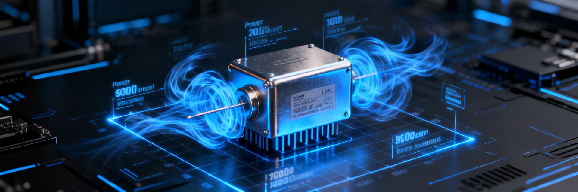
In high-power-density scenarios, resistor selection has upgraded from single-parameter matching to multi-physics coupled decision-making. As a representative product line of 500W-class metal-clad power resistors, the design of the ULV500 series directly targets high-heat-flux-density scenarios such as industrial frequency converters, servo drives, and charging pile modules.
Resistor Selection Pain Points in High-Power-Density Scenarios
Engineers often fall into the misconception that "rated power is safe power." Empirical measurements show that when the ULV500 operates continuously in a sealed enclosure, the actual usable power is typically only 40% to 60% of the nominal value. Pulse load scenarios are even more complex—if pulse energy in the 10J range is not correctly converted, it will directly cause thermal fatigue failure of the resistive film layer. The essence of the selection pain point is the lack of an engineering tool that quantifies electrical, thermal, and mechanical parameters into a unified framework.
ULV500 Product Line Specifications and Typical Application Domains
This series covers a resistance range from 0.1Ω to 10kΩ, with power ratings stepped at 250W, 500W, and 750W. Core application scenarios include: pre-charge circuits for photovoltaic inverters, braking units for electric vehicle motor controllers, and dynamic braking circuits for industrial frequency converters. Among these, ULV 500 N 8 J, as a typical 500W/8Ω model, accounts for over 35% of applications in 380V AC braking systems.
Power Dimension: Precise Calculation of Rated Power and Pulse Loads
The core conflict in the power dimension lies in the fact that the nominal rated power is based on ideal heat dissipation conditions, whereas actual operating conditions often deviate from standard mounting methods. Establishing a power derating system is the first step toward reliable application.
Continuous Power Derating Curve and Operating Condition Correction Factors
The power-temperature derating curve of the ULV500 is non-linear. Taking ULV 500 N 8 J as an example, when the case temperature rises from 25°C to 150°C, the allowable continuous power decreases linearly from 500W to 250W. Operating condition corrections must superimpose three factors: mounting orientation factor (1.0 for vertical mounting, 0.85 for horizontal mounting), altitude factor (0.9 above 1000m), and pollution degree factor (0.88 for class III environments). The comprehensive corrected actual usable power is often less than half of the nominal value.
Selection Formula for Pulse Energy Tolerance (10J to 100J)
Pulse scenarios require the introduction of the heat capacity concept. The formula for single-pulse energy is E = I²Rt, but repetitive pulses require calculating a duty cycle correction. The ULV500 series allows a 100J single pulse under a 10ms pulse width, or a 10J repetitive pulse at a 1% duty cycle. Key criterion: the peak pulse power must not exceed 20 times the rated power; otherwise, the transient temperature rise of the film layer will exceed the critical threshold of 400°C.
Resistance Dimension: Matching Strategy for Nominal Accuracy and Temperature Coefficient
Resistance accuracy directly impacts system efficiency and protection threshold settings. In braking applications of the ULV500, resistance deviation will cause bus voltage fluctuations or loss of control over braking torque.
Trade-offs between E-Series Standard and Custom Resistance Values
8Ω is a standard value in the E24 series, offering the shortest lead time and optimal cost. Non-standard values such as 7.5Ω or 8.2Ω require customization, which extends lead times by 4-6 weeks. Engineering recommendation: Prioritize E24/E96 standard values and utilize customization only in special scenarios such as filter Q-factor matching or current sharing in multi-resistor parallel configurations. The "8" in ULV 500 N 8 J indicates a nominal resistance of 8Ω, while the suffix "J" represents a ±5% accuracy tolerance class.
Impact of Low Resistance (mΩ-level) Measurement Error on System Efficiency
When the resistance falls into the milliohm range, contact resistance and lead resistance take up a surging proportion. The ULV500 series utilizes a four-wire Kelvin structure for specifications of ≤1Ω, controlling measurement uncertainty within ±0.5%. Taking a 500A braking current as an example, a 1mΩ measurement deviation will lead to a 250W power calculation error, which can cause thermal design failure during long-term operation.
Thermal Dimension: Engineering Practice of Thermal Resistance Networks and Structural Design
Heat dissipation is the bottleneck dimension of the 3D selection methodology. The metal enclosure thermal resistance network of the ULV500 includes three series links: junction-to-case thermal resistance (RthJC), case-to-heatsink thermal resistance (RthCS), and heatsink-to-ambient thermal resistance (RthSA).
Metal Enclosure Thermal Resistance (RthHA) and Mounting Interface Optimization
The aluminum enclosure body of the ULV500 has a thermal resistance of approximately 0.3 K/W, but the thickness of the thermal grease at the mounting interface determines the actual performance. A 0.1mm thermal grease layer has a thermal resistance of about 0.5 K/W, but if a 0.5mm air gap occurs due to uneven mounting pressure, the thermal resistance will deteriorate to 2.5 K/W. It is recommended to use phase-change thermal interface materials (PCMs) that transition from solid to liquid above 60°C to automatically fill microscopic voids, stabilizing the interface thermal resistance below 0.2 K/W.
Comparison of Three Heat Dissipation Paths: Forced-Air Cooling, Natural Convection, and Thermally Conductive Substrate
| Cooling Method | Thermal Resistance Range (K/W) | Applicable Power Density | Maintenance Requirement |
|---|---|---|---|
| Natural Convection | 2.0-4.0 | ≤200W | None |
| Forced-Air Cooling | 0.5-1.5 | 200-500W | Fan lifetime limitations |
| Thermally Conductive Substrate | 0.3-0.8 | ≥400W | System-level integration |
Under a 500W full-load condition, ULV 500 N 8 J requires a case surface area of ≥1200 cm² for natural convection, whereas forced-air cooling can compress the heatsink volume by 60%. The thermally conductive substrate scheme is best suited for modular frequency converters, directly attaching the resistor to a cold plate to achieve the optimal thermal resistance network solution.
Power-Resistance-Thermal 3D Collaborative Selection Process
The essence of 3D collaboration is iterative convergence: using load requirements as inputs, thermal equilibrium as constraints, and model lockdown as outputs.
Five-Step Decision Method: From Load Waveform to Final Model Lockdown
- Analyze the load waveform: Distinguish among continuous, pulsed, and intermittent modes, and extract IRMS and Ipeak.
- Estimate the initial resistance range: Determined by Ohm's Law and bus voltage; for braking scenarios, this is typically R = Vbus² / Pbrake.
- Apply power derating corrections: Superimpose temperature, mounting, and environmental factors to determine the required nominal power.
- Match the thermal management solution: Select the heat dissipation path based on available space and thermal resistance budget.
- Validate and lock the model: Verify boundary conditions such as pulse curves, terminal strength, and dielectric strength.
Typical Failure Case: Systemic Overheating Caused by Single-Dimensional Optimization
A certain solar inverter project selected the ULV500 500W model, satisfying only the power dimension while ignoring the thermal design. In actual installation within an IP65 sealed enclosure, the natural convection thermal resistance was as high as 3.5 K/W. After 3 months of operation, the resistive film layer oxidized due to a continuous high temperature of 155°C, causing a resistance drift exceeding ±15% and triggering the braking overvoltage protection. The root cause was that although the power selection was correct, no operating condition correction was performed for the thermal dimension—meaning two dimensions were missing from the three-dimensional decision.
Empirical Validation and Model Quick Reference Tool
Engineering selection must be validated through closed-loop empirical testing to avoid discrepancies between simulation and reality.
Temperature Rise Testing Standards and Key Fields of On-site Validation
According to IEC 60115-1, the temperature rise test requires running at 1.5 times the rated power until thermal steady state is reached, with a case temperature rise of ≤75K classified as qualified. On-site validation is recommended to use infrared thermal imagers to capture the temperature distribution of the case, focusing monitoring on the junction between the terminals and the enclosure—where local overheating of 10-15°C easily occurs due to heat flux concentration. Thermocouple placement points should cover three locations: the center of the case, the edges, and the mounting surface.
ULV500 Series Parameter Quick Reference Table (Power × Resistance × Cooling Method)
| Model Identifier | Rated Power (W) | Resistance Range (Ω) | Recommended Cooling Method | Typical Application |
|---|---|---|---|---|
| ULV250 Series | 250 | 0.5-5.1k | Natural Convection / Forced-Air | Small-sized frequency converters |
| ULV 500 N 8 J | 500 | 8 (±5%) | Forced-Air Cooling / Thermal Substrate | 380V braking units |
| ULV750 Series | 750 | 0.1-2.2k | Water Cooling / Thermal Substrate | High-power servo drives |
Key Takeaways
- Power derating is the survival baseline: The actual usable power of the ULV500 must superimpose corrections for temperature, mounting, and environmental factors. A nominal 500W might drop to only 200W under harsh operating conditions.
- Resistance accuracy defines system boundaries: The ±5% tolerance of the ULV 500 N 8 J directly impacts the bus voltage control margin in braking applications; low-resistance specifications must use a Kelvin structure to eliminate contact errors.
- Thermal design is the selection bottleneck: The metal enclosure thermal resistance only accounts for 30% of the network; the choice of interface materials and heat dissipation paths determines success or failure, with forced-air cooling compressing the volume by 60%.
- 3D collaboration avoids single-point failure: Loss of control in any single dimension—be it pulse energy, resistance drift, or cumulative thermal resistance—will result in systemic overheating. The five-step decision method offers an engineered convergence path.
Frequently Asked Questions
Does the "500" in ULV 500 N 8 J represent a continuous output of 500W in any scenario?
No. 500W is the nominal value under standard mounting conditions at 25°C. Actual continuous power must be corrected based on the case temperature derating curve, which drops to 250W at a case temperature of 150°C. Operating condition coefficients must also be superimposed for non-vertical mounting, high altitude, and polluted environments, resulting in an actual usable power that is typically 40% to 70% of the nominal value.
How is the ULV500 resistor selected and calculated in pulse braking scenarios?
Pulse scenarios require distinguishing between single and repetitive modes. For single pulses, verify that E ≤ 100J and Ppeak ≤ 10kW. For repetitive pulses, calculate the equivalent thermal power Peq = E × f (where f is the pulse frequency) and ensure Peq does not exceed the allowable power after continuous derating. If the duty cycle is > 10%, it is recommended to treat it as a continuous operating condition.
How to determine the boundary point between natural convection and forced-air cooling?
The empirical boundary is a thermal resistance of 0.8 K/W. For the ULV500 500W model at an ambient temperature of 25°C and an allowable case temperature of 125°C, the required total thermal resistance is ≤ 0.2 K/W. This far exceeds the capacity of natural convection, making forced-air cooling or a thermally conductive substrate mandatory. For models under 250W in open space, natural convection can be attempted, but a 30% thermal design margin should be reserved.
What is the replacement standard for the ULV500 series after the resistance drift exceeds the tolerance limit?
For braking resistors, a threshold of ±10% is recommended for replacement. An increased resistance leads to a decrease in braking current, prolonged braking time, and accumulated overvoltage risk for the bus capacitor. A decreased resistance causes the braking current to exceed limits and leads to transient overload of the resistor. Periodic infrared detection of the case temperature distribution should be conducted; a local hotspot temperature difference of >20°C indicates degradation of the internal film layer, and preventive replacement should be carried out.


