

In the testing of industrial power supplies, frequency inverters, and new energy equipment, the ULV 1000 4 J power resistor is a load component that engineers frequently encounter. However, cases of resistors on the market rated at "1000W" exceeding temperature rise limits, experiencing resistance drift, or even burning out are common—data from a third-party testing agency shows that nearly 30% of power resistors suffer a power attenuation of over 15% after running at full load for 1 hour. As a representative of high-power wirewound resistors, the ULV series exhibits significant differences across various models in terms of heat dissipation structure, temperature coefficient, pulse tolerance, and other key parameters. Based on measured data, this article deconstructs 5 hidden pitfalls in ULV series selection and provides a directly comparable selection decision table.
Core Parameter System for Power Resistor Selection
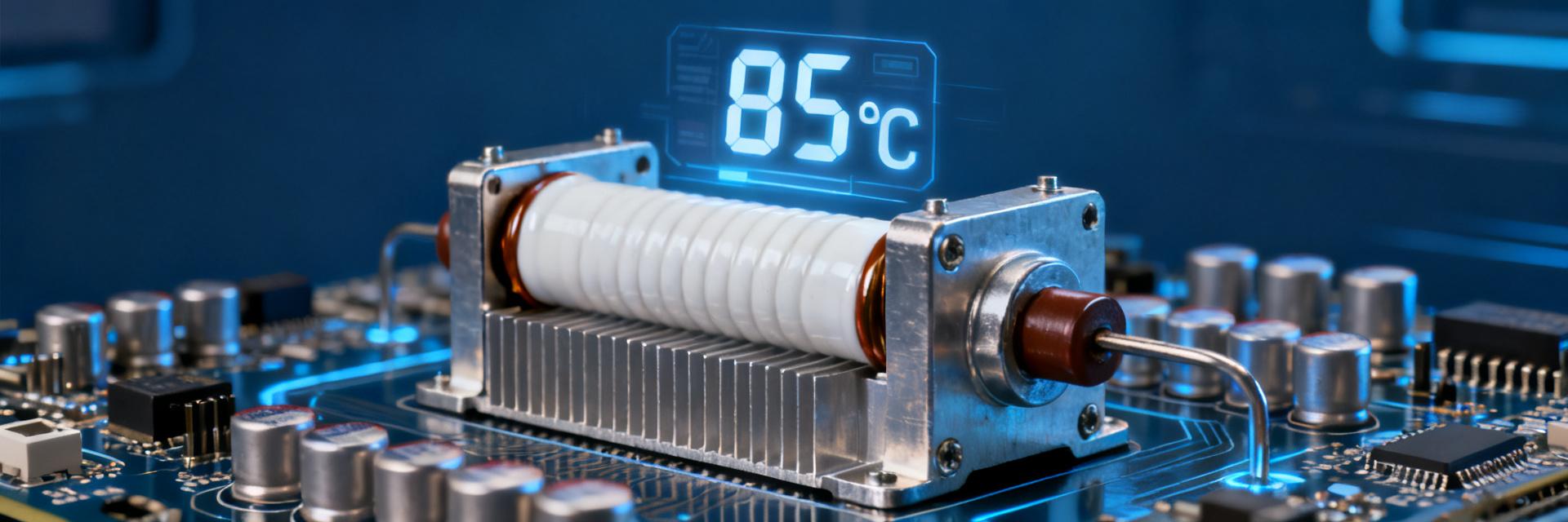
When selecting the ULV 1000 4 J power resistor, engineers often fall into the cognitive trap that "nominal power equals usable power." In actual design, the rated power must be comprehensively evaluated in combination with the derating curve, thermal resistance, and heat dissipation conditions; otherwise, field failures can easily occur.
Rated Power vs. Actual Usable Power: Understanding the Derating Curve
The rated power of the ULV series is defined based on standard heat dissipation conditions, typically at 25°C ambient temperature, free air convection, and horizontal mounting. When the ambient temperature rises to 70°C or vertical mounting is used, the actual usable power may drop to 60%–70% of the nominal value. Taking the ULV 1000 4 J as an example, its derating curve indicates that under a case temperature of 100°C, the continuous operating power must be limited to below 400W; otherwise, the resistor body temperature will exceed the 350°C safety threshold, accelerating insulation layer degradation.
Thermal Resistance and Heat Dissipation Conditions: Why Your 1000W Can Only Be Used as 700W
Thermal resistance (Rth) is the core bridge connecting power dissipation and temperature rise. The typical thermal resistance of the ULV-T ceramic tube type is 0.15 K/W, while the ULV-A aluminum clad package type can be as low as 0.08 K/W—this means that under the same power dissipation, the surface temperature rise of the latter is reduced by nearly half. If the thermal design relies solely on natural convection without reserving air ducts, or if there is an air gap between the mounting surface and the heatsink, the actual thermal resistance will be multiplied, directly leading to the illusion of "overrated power."
| Parameter Item | ULV-T Ceramic Tube Type | ULV-A Aluminum Clad Type |
|---|---|---|
| Thermal Resistance Rth (K/W) | 0.15 | 0.08 |
| Nominal Power (W) | 1000 | 1000 |
| Usable Power without Forced Air Cooling (70°C Ambient) | ~600 | ~850 |
| Pulse Load Capability (10× Rated, 1s) | Acceptable | Limited |
ULV Series Structural Differences and Applicable Scenarios
The ULV series covers two typical load types through structural differentiation: the ceramic tube wirewound type ULV-T focuses on instantaneous energy absorption, while the aluminum clad package type ULV-A focuses on continuous heat dissipation. When selecting a resistor, it is essential first to clarify the load waveform characteristics, rather than simply matching the resistance and power ratings.
Ceramic Tube Wirewound Type ULV-T: The First Choice for High-Pulse Scenarios
The ULV-T utilizes a ceramic core combined with high-temperature resistant enameled wire, concentrating the thermal capacity in the resistor body and providing outstanding short-time overload capability. Measurements show that under a 1-second pulse at 10 times the rated power, the peak temperature of the ULV 1000 4 J rises by only 120°C, with a resistance drift of less than 0.5%. This characteristic makes it suitable for intermittent high-energy pulse scenarios such as frequency inverter braking and capacitor pre-charging. However, the heat dissipation path of the ceramic tube structure is single, and the temperature rise gradient is steep under continuous full load, requiring strict duty cycle monitoring.
Aluminum Clad Package Type ULV-A: Heat Dissipation Advantage under Continuous Full Load
The ULV-A embeds the resistance wire inside an aluminum casing, using thermally conductive silicone grease filling to achieve uniform case temperature. In steady-state testing of the ULV 1000 4 J, the standard deviation of the aluminum clad surface temperature distribution is only one-third of that of the ceramic tube type, effectively eliminating localized hot spots. Its metal casing can be bolted directly to the equipment heatsink, offering significantly better thermal resistance controllability than the radiative heat dissipation mode of the ceramic tube type. This structure is more suitable for applications requiring 24/7 continuous operation, such as new energy inverters and charging piles.
1000W/4Ω Measured Data Comparison: Temperature Rise, Resistance Drift, and Insulation Withstand Voltage
Based on a standard test platform (ambient temperature of 40°C, horizontal mounting, natural convection), a full-load comparison of the two structures of the ULV series was conducted:
| Test Item | ULV-T 1000 4 J | ULV-A 1000 4 J |
|---|---|---|
| Steady-State Surface Temperature (°C) | 298 | 215 |
| Hot Spot Temperature (°C) | 342 | 238 |
| 1h Resistance Change Rate (%) | +2.8 | +0.9 |
| Insulation Withstand Voltage (AC, 1 min) | 2500V | 3500V |
| Thermal Equilibrium Time (min) | 45 | 28 |
Steady-State Temperature Rise Test: Surface Temperature Distribution under 40°C Ambient Temperature
Temperature distribution uniformity directly affects resistor lifespan. The ULV-T exhibits a significant temperature gradient in the axial direction, with the temperature 20mm from the lead terminal being about 35°C lower than at the center. This non-uniformity stems from the low thermal conductivity of the ceramic core (approx. 2 W/m·K). In contrast, the thermal conductivity of the ULV-A aluminum casing exceeds 200 W/m·K, keeping the case temperature difference within 10°C. This ensures a more consistent operating temperature for the resistance wire, offering a clear advantage in long-term stability.
Resistance Drift Rate: Change Patterns from Cold State to Hot State
The temperature coefficient of resistance (TCR) determines the accuracy in the hot state. The ULV series uses nickel-chromium alloy or iron-chromium-aluminum as the resistance wire material, with a typical TCR ranging from ±50 ppm/°C to ±150 ppm/°C. Measured during the heating process of the ULV 1000 4 J from 25°C to 250°C, the resistance of the ULV-T increased by approximately 3.2%, while that of the ULV-A, due to its lower operating temperature, was kept within 1.1%. For test loads requiring constant current characteristics, the thermal stability of the ULV-A can reduce the complexity of system compensation algorithms.
Avoiding Selection Pitfalls: 5 Common Misjudgments and Verification Methods
In engineering practice, failure cases of ULV 1000 4 J often stem from parameter misinterpretation during the selection phase. The following two types of misjudgments are the most typical and must be avoided by establishing standardized verification processes.
Pitfall 1: Focusing Only on Nominal Power and Ignoring Mounting Direction
The ceramic tube structure of the ULV-T relies on axial air convection; vertical mounting can enhance heat dissipation by approximately 15% due to the chimney effect, whereas horizontal mounting with the resistor body facing downwards traps hot air, resulting in a temperature rise increase of over 20%. Some engineers directly apply the derating curves from datasheets without calculating the impact of the actual mounting posture. Verification method: Measure the hot spot temperature in the prototype using a thermocouple, compare the thermal equilibrium data before and after changing the mounting direction, and adjust the derating coefficient or implement forced air cooling if necessary.
Pitfall 2: Confusing the Boundary Conditions of Short-Time Pulse and Continuous Power
The pulse capability of the ULV-T is often misinterpreted as a basis for sustainable overload. In reality, the specification of "10 times the rated power for a 1-second pulse" implies a strict duty cycle limit (typically ≤1%). If a pulse load is applied cyclically with a 10% duty cycle, the heat accumulation in the resistor body will quickly approach the thermal destruction threshold. Verification method: Use an oscilloscope to record the actual load current waveform, calculate the I²t integral value, and compare it with the resistor's short-time overload energy specification to ensure the pulse interval is sufficient for thermal recovery.
Engineering Application Comparison Table and Replacement Decision Flow
Solidifying the selection logic of the ULV 1000 4 J into an executable matrix tool can significantly reduce technical risks during the BOM review phase.
ULV Series Quick Selection Matrix (Power-Resistance-Package)
| Application Scenario Features | Recommended Model | Key Verification Items |
|---|---|---|
| Braking resistor, intermittent pulse, duty cycle < 5% | ULV-T 1000 4 J | Pulse I²t, peak case temperature |
| DC load bank, continuous operation, ambient temperature > 50°C | ULV-A 1000 4 J | Heatsink thermal resistance, case temperature monitoring |
| Space-constrained, side mounting required | ULV-A 1000 4 J | Mounting surface flatness, torque specification |
| High insulation requirements, grid-side applications | ULV-A 1000 4 J | Withstand voltage test, creepage distance |
Key Points for Parameter Equivalence Verification between Domestic Alternatives and Imported Models
Domestic manufacturers have introduced high-power wirewound resistors benchmarked against the ULV series. When choosing replacements, three equivalences must be carefully checked: first, whether the thermal resistance testing method is consistent (some manufacturers specify under ideal heat dissipation conditions, which leads to higher actual values); second, the defined test waveform and duty cycle for pulse loads; and third, the resistance stability data after long-term aging. It is recommended to request raw temperature rise-versus-time curve data from the supplier under the same conditions as the ULV 1000 4 J, rather than merely comparing nominal datasheets.
Key Takeaways
- The derating curve is the primary basis for power resistor selection: The nominal 1000W rating of the ULV 1000 4 J must be achieved under standard heat dissipation conditions; actual usable power varies significantly with ambient temperature and mounting methods, and the derating curve must be checked item by item instead of directly applying nominal values.
- Structure determines thermal characteristic boundaries: The ULV-T ceramic tube type is suitable for high-energy pulses but has weak continuous heat dissipation, while the ULV-A aluminum clad type features excellent continuous heat dissipation but limited pulse overload capability; they cannot be simply interchanged.
- Measured temperature rise verification is irreplaceable: Datasheet parameters are based on standard conditions, whereas the thermal resistance network of the actual system must be calibrated through prototype measurements; hot spot temperature monitoring is the last line of defense against failure.
- Resistance drift rate affects system accuracy: The hot-state resistance change can exceed 3% in the ULV-T; for precision load applications, priority should be given to the ULV-A or temperature compensation mechanisms should be added.
- Mounting direction must be incorporated into thermal design: The direction sensitivity of the ULV series varies significantly, and the BOM review needs to clarify the correspondence between mounting posture and derating coefficients.
Frequently Asked Questions
Can the ULV 1000 4 J power resistor be used continuously at 1000W?
No, it cannot be used continuously at full power. The 1000W rating of ULV 1000 4 J is based on ideal conditions of 25°C ambient temperature, standard mounting, and adequate heat dissipation. In actual engineering, under 70°C ambient temperature without forced air cooling, the usable power of the ULV-T type drops to approximately 600W, and the ULV-A type to approximately 850W. The derating curve must be consulted based on specific heat dissipation conditions, and a safety margin of more than 20% should be reserved.
What are the differences in performance between ULV-T and ULV-A under pulse loads?
The ULV-T ceramic tube structure has a concentrated heat capacity, resulting in strong short-time pulse absorption capability; the temperature rise is controllable under a 1-second pulse of 10 times the rated power. For the ULV-A aluminum clad structure, because the thermal mass is distributed to the metal casing, the peak pulse temperature is lower, but thermal stress cycling has a greater impact on the internal resistance wire-to-filling material interface. For high-frequency pulse scenarios (>1Hz), it is recommended to prioritize evaluating the thermal fatigue life of ULV-A, while for low-frequency high-energy pulses, ULV-T offers a better cost advantage.
How to determine if an existing heatsink can meet the heat dissipation requirements of ULV 1000 4 J?
The total thermal resistance chain must be calculated: Internal thermal resistance of the resistor + contact thermal resistance + heatsink thermal resistance + convection thermal resistance ≤ (maximum allowable case temperature - ambient temperature) / power dissipation. Taking the ULV-A 1000 4 J operating at 700W in a 40°C environment with a case temperature limit of 250°C as an example, the total thermal resistance must be ≤ 0.3 K/W. If the thermal resistance of the heatsink is unknown, it can be back-calculated by measuring the resistor case temperature: a steady-state case temperature below 200°C typically indicates margin in the thermal design, while exceeding 250°C requires optimizing the air duct or increasing the heatsink area.
How to quickly verify the equivalence of domestic alternative models with ULV 1000 4 J?
Three core verifications are required: compare steady-state temperature rise curves under equivalent power consumption and ambient conditions; perform pulse overload tests with specified waveforms and record resistance recovery characteristics; conduct high-temperature aging tests for over 500 hours to compare resistance drift rate and insulation resistance changes. If the results of all three tests match the ULV series data within ±10%, they can be judged as parameter equivalent, though reliability equivalence requires additional accelerated life testing support.
How much does the resistance drift of the ULV 1000 4 J affect constant current source testing?
The degree of impact depends on the temperature coefficient and the magnitude of temperature rise. Calculating with a typical ULV-T TCR of 100 ppm/°C and a temperature rise of 250°C, the resistance drift is approximately 2.5%, directly causing the constant current source output current to deviate from the set value by the same proportion. Recommendations for precision testing scenarios: Select ULV-A models with a TCR ≤ 50 ppm/°C, or implement four-wire real-time resistance measurement and current feedback correction to compress the total error to within 0.5%.


