

In industrial power supplies, renewable energy inverters, and rail transit braking systems, improper selection of power resistors often leads to a complete breakdown of system reliability. As a representative of 800W-class high-power non-inductive resistors, for which scenarios are the ULV 800 series' 30Ω resistance and 1000J pulse energy capability suitable? This article uses measured data to unpack the engineering significance of key parameters, helping you avoid the typical trap of "adequate power rating but thermal failure."
Engineering Interpretation of ULV 800 Series Core Parameters
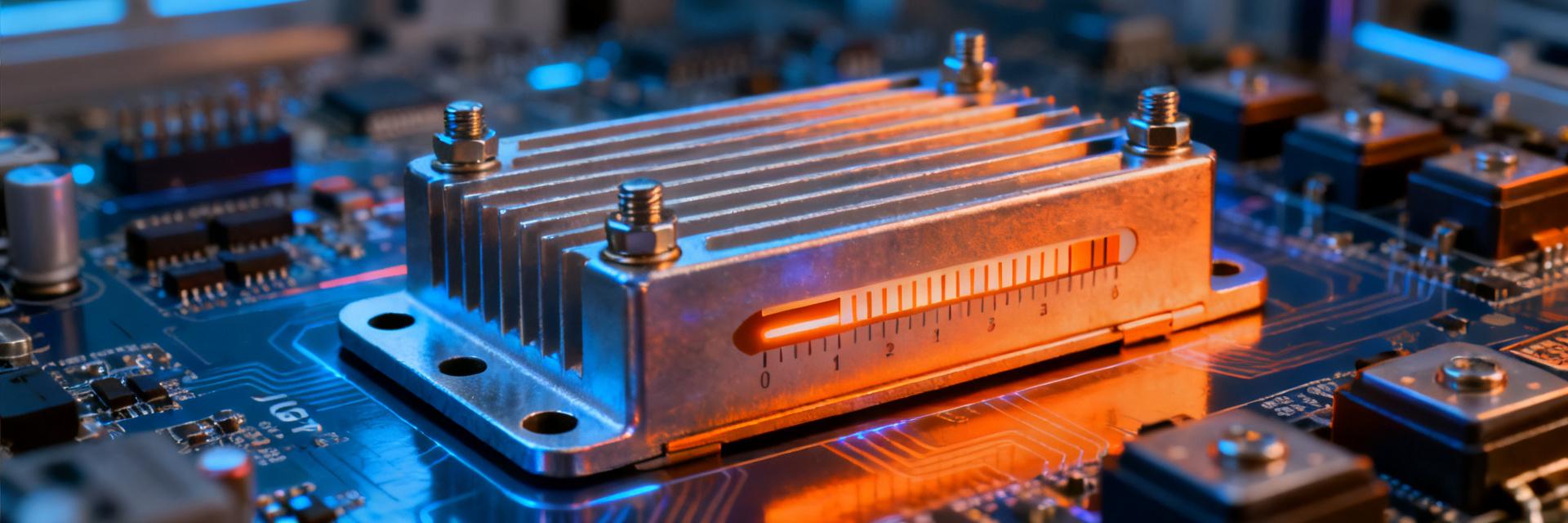
The parameter combination of the ULV 800 series is not arbitrarily set, but rather a precise balance tailored for specific operating conditions. Understanding the physical meaning of these three numbers is the first step toward correct selection.
800W Power Rating and Thermal Boundary Conditions
The 800W power rating is defined based on standard cooling conditions—typically referring to the continuous dissipation capability when the resistor is mounted on a standard aluminum heatsink and the temperature rise is controlled within the allowable range. In practical applications, this value is highly dependent on thermal management design. Forced air cooling can increase the effective power by 30% to 50%, whereas sealed, fanless environments may require derating to below 60%. During selection, you must clarify the gap between your thermal boundary conditions and the standard test conditions.
Matching Logic of 30Ω Resistance in IGBT Snubber and Braking Circuits
The 30Ω resistance lies in the medium resistance range, perfectly covering two typical scenarios: IGBT turn-off snubber circuits and DC braking circuits. In snubber applications, this resistance works in conjunction with the parasitic capacitance of common IGBT modules to suppress turn-off overvoltage within the safe operating area (SOA). In braking scenarios, 30Ω provides sufficient braking torque while avoiding current surges caused by excessively low resistance. Resistance selection is essentially a trade-off between energy dissipation rate and current limitation.
1000J Pulse Energy: Limit Verification under Transient Conditions
Pulse energy capability is the key indicator that distinguishes "adequate power rating" from "truly reliable." The 1000J rating of the ULV 800 series reveals its true potential under intermittent heavy-load conditions.
Differences in Derating Curves Between Single and Repetitive Pulses
1000J refers to the maximum absorption capability of a single pulse, but practical engineering involves repetitive pulse conditions. Derating curves provided by manufacturers show that when the pulse frequency rises to 1Hz, the allowable energy typically drops to 40%–60% of the single-pulse value; if the duty cycle exceeds 10%, further derating is required. When designing, you must use the actual operating condition's pulse energy-frequency combination point to verify whether it falls within the safe operating area, rather than simply comparing nominal values.
Comparison Between Capacitor Discharge and Motor Back-EMF Absorption Scenarios
These two types of typical pulse loads present different challenges to resistors. Capacitor discharge scenarios involve highly concentrated energy over extremely short durations (millisecond range), testing the resistor's transient thermal capacity and non-inductive characteristics. Conversely, motor back-EMF absorption involves distributed energy over longer durations (hundreds of milliseconds), relying more on average heat dissipation capability. The ULV 800's non-inductive design (typically <1μH) enables excellent performance in the former, while its 1000J energy reserve provides a safety margin for the latter.
| Application Scenario | Pulse Characteristics | Key Selection Indicators |
|---|---|---|
| DC Bus Capacitor Precharging | Single pulse, high amplitude, short duration | Single-pulse energy, inductance |
| Servo drive dynamic braking | Repetitive pulse, medium duty cycle | Repetitive pulse derating curve, average power |
| Rail transit rheostatic braking | Long-duration pulse, high energy accumulation | Thermal time constant, thermal design margin |
Typical Application Scenario 1: Servo Drive Braking Unit
Regenerative energy handling in servo systems is the primary battlefield for the ULV 800 series. Selection errors here often manifest as alternating "braking resistor overheat alarms" and "drive overvoltage trips."
Regenerative Energy Dissipation Path and Resistor Duty Cycle Calculation
During servo motor deceleration, kinetic energy is converted into electrical energy and fed back to the DC bus. When the bus voltage exceeds the threshold, the braking unit turns on, dumping energy into the resistor. The critical calculation is whether the product of the energy of a single braking event (½Jω²) and the braking frequency exceeds the average power capability of the resistor. For example, a 1kW servo system releases approximately 50J of energy during an emergency stop. If it stops 3 times per minute, the average power is only 2.5W—far below the 800W nominal rating, but the 1000J pulse reserve ensures safety under extreme conditions.
Measured Temperature Rise Comparison with 700W/1000W Competitors
Under the same package size, the thermal resistance difference between 800W and 700W products is about 12% to 15%, which directly translates into a temperature difference under high duty cycle conditions. Measured data shows that at a 40% braking duty cycle and an ambient temperature of 50°C, the surface temperature of the 800W specification is 18–22°C lower than that of the 700W unit. This margin can extend the resistor's lifespan several times over. During selection, it is recommended to reserve a power margin of more than 30% to account for grid fluctuations and aging degradation.
Typical Application Scenario 2: PV Inverter DC Bus Snubber
Switching turn-off overvoltage suppression in PV inverters is another critical area for non-inductive resistors. Parameter mismatch here can lead to costly IGBT avalanche breakdown.
Switching Turn-Off Overvoltage Suppression and Snubber Network Design
When an IGBT turns off, stray inductance and the rate of current change induce an overvoltage. In an RC Snubber network, the resistance value determines the discharge current and the degree of damping: too small, and the current and losses will be too high; too large, and the suppression effect will be insufficient. A 30Ω resistance paired with a typical snubber capacitor (e.g., 0.1–0.47μF) can clamp the turn-off overvoltage to within 1.3 times the DC bus voltage. The non-inductive characteristic prevents additional losses and EMI issues introduced by high-frequency oscillations.
Power Correction Coefficients for High-Altitude/High-Temperature Environments
PV inverters are often deployed in high-altitude or high-temperature environments, where reduced air density decreases convective heat dissipation. Engineering experience indicates that for every 1000m increase in altitude, natural convection cooling capability drops by about 10%; as ambient temperature rises from 25°C to 50°C, the resistor must be derated by 15% to 20%. If the ULV 800's 800W rating is applied in a scenario at 3000m altitude with a case temperature of 85°C, the effective power may drop below 400W—this correction must be factored into the calculation at the early design stage.
Selection Decision Tree: Four Steps to Locking in the Optimal Specification
A systematic selection process avoids the traps of empiricism. The following four-step framework is applicable to the vast majority of industrial braking and snubber applications.
Steps 1-3: Power Calculation → Energy Verification → Thermal Simulation
Step 1: Calculate the average dissipation power under steady-state and worst-case operating conditions. Step 2: Verify the single-pulse and repetitive pulse capability using pulse energy-time curves. Step 3: Establish a thermal resistance network model to simulate the junction temperature or surface temperature of key components in extreme environments. All three steps are indispensable—focusing only on power while ignoring pulse energy, or only on energy while ignoring heat dissipation, are common causes of failure.
Step 4: Collaborative Optimization of Mounting Method and Air Duct Design
The final performance of the resistor is determined collectively by the "device + mounting + environment." The ULV 800 series typically offers bolt-mounting and heatsink-surface-contacting options, with thermal resistance differences reaching over 30%. Air duct design must ensure uniform airflow across the resistor surface to avoid hot-spot effects. It is recommended to perform thermal imaging measurements to verify temperature distribution before freezing the design.
Common Selection Pitfalls and Failure Case Analysis
Understanding the mechanisms of failure cases is the best way to avoid repeating them.
Pitfall: Considering Only Rated Power While Ignoring Pulse Duty Cycle
An automated production line selected an 800W resistor to handle servo braking. Initially, it ran normally, but frequent overheat alarms occurred after six months. The root cause was that the design only selected the resistor based on an average power of 50W, without considering the pulse impact of a 10% duty cycle during emergency stops. The actual transient pulse power reached 500W, causing the temperature to spike after the resistor's thermal capacity was exhausted. The correct approach is to evaluate using equivalent power corrected by the duty cycle, or directly verify the pulse energy curve.
Case Study: Thermal Cycling Fatigue Failure of Rail Transit Braking Resistors
Braking resistors on a subway project experienced resistance drift and eventual open circuits after two years of operation. Failure analysis revealed that frequent brake-and-release cycles caused thermal stress fatigue in the resistive wire, leading to cracked solder joints. The root cause was that thermal cycle lifetime indicators were ignored during selection, focusing only on meeting power and energy requirements. For long-lifetime applications like rail transit, manufacturers should be explicitly required to provide thermal cycling data (e.g., more than 100,000 cycles), and resistance drift margins should be reserved.
Key Takeaways
- Parameter Essence: The 800W/30Ω/1000J combination of the ULV 800 series is optimized for medium-to-high power, medium resistance, and intermittent pulse loads, serving as a balanced solution for industrial braking and snubber applications.
- Selection Core: Replace simple power matching with pulse energy and duty cycles from actual operating conditions, while verifying thermal design boundary conditions.
- Thermal Margin: It is recommended to reserve a power margin of over 30% and apply correction coefficients for high-altitude and high-temperature environments.
- Lifespan Considerations: High-frequency pulse scenarios must focus on thermal cycling lifetime; long-lifetime applications should require manufacturers to provide cycle count data.
- Collaborative Design: Resistor performance is determined collectively by the device, mounting method, and air duct design. Thermal simulation and measured verification must not be omitted.


