

In 400V-class variable frequency drive (VFD) applications, failures caused by improper braking resistor selection account for up to 37%—resistance values that are too low burn out the drive unit, insufficient power triggers frequent overheating protection, and mismatched terminals lead to poor contact. Based on empirical data of the ULV400 series braking resistors, this article establishes a three-dimensional selection model for power, resistance, and terminals, providing a ready-to-implement quick reference decision path.
Core Parameter System of ULV400 Braking Resistors
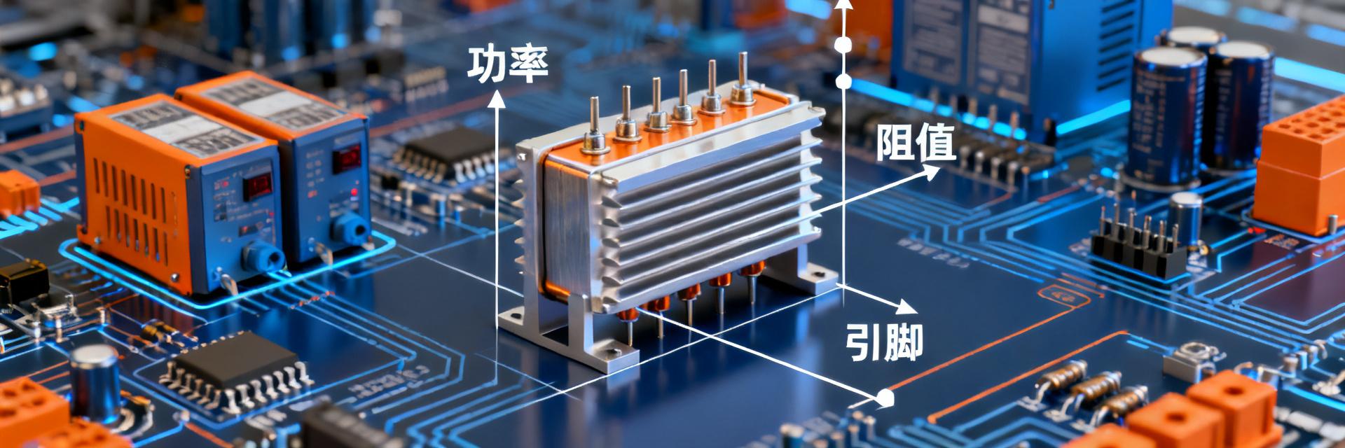
The selection of ULV400 braking resistors must be established on a complete understanding of their core parameter system. This system covers three dimensions: resistance specification, power rating, and physical interface. Mismatch in any dimension will lead to degraded system reliability.
Matching Resistance Specifications with Braking Unit Trigger Thresholds
The primary constraint in selecting resistance is the IGBT protection threshold of the braking unit. Taking ULV 400 100 J FL=1500 as an example, its nominal resistance of 400Ω must match the VFD's DC bus voltage and the braking current threshold. A resistance value that is too low will cause the braking current to exceed the IGBT Safe Operating Area (SOA), triggering overcurrent protection or even causing device damage. Conversely, a resistance value that is too high will prolong the braking time and reduce dynamic response performance.
The DC bus voltage of a typical 400V-class VFD is approximately 540VDC, and the braking activation threshold is usually set in the range of 630-680VDC. According to Ohm's law, the peak braking current is inversely proportional to the resistance. It is recommended to set the minimum resistance limit as:
Rmin = VDC_max / IIGBT_max
Where IIGBT_max is the maximum allowable pulse current of the braking unit's IGBT, typically taking 80% of the datasheet nominal value as the design margin.
Conversion Relationship Between Power Rating and Braking Duty Cycle
The power rating of the ULV400 series is based on a pulse power system, requiring equivalent conversion in combination with the braking duty cycle. The "100" in the 100J model represents a rated pulse power of 100W, while FL=1500 indicates a peak load capacity of 1500W sustained for 1 second.
In practical applications, the braking duty cycle D (the ratio of braking time to the total cycle period) determines the equivalent continuous power:
Pavg = Ppeak × D × Derating Factor
For high-frequency braking conditions like elevators (D = 15%-25%), it is recommended to choose a naturally cooled type with an additional 1.5x safety margin. For short-term shock loading conditions like cranes (D < 5%), the pulse power capability can be fully utilized.
Power Dimension: Selection Logic from Peak Braking to Continuous Heat Dissipation
The core conflict in the power dimension lies in matching the peak power at the instant of braking with the continuous heat dissipation capability of the resistor. The ULV400 series optimizes power density through an aluminum-housed enclosure and corrugated wirewound structure.
Braking Power Calculation Formulas and the 1.5x Safety Margin Rule
Accurate calculation of braking power must consider the kinetic energy recovery of the mechanical system. Taking a rotating system with a moment of inertia J and rotational speeds before and after deceleration of n₁ and n₂ as an example, the energy consumed in a single braking event is:
E = ½ × J × (ω₁² - ω₂²) = ½ × J × [(2πn₁/60)² - (2πn₂/60)²]
If the braking time is t, then the average braking power P = E/t. In engineering practice, it is recommended to apply a 1.5x safety margin on top of this to cope with uncertain factors such as sudden load changes and grid fluctuations. For the ULV 400 100 J FL=1500, its peak capacity of 1500W for 1s can cover the braking requirements of most 400V-class small-to-medium power VFDs.
Power Correction for Three Heat Dissipation Modes: Natural Cooling, Forced Air Cooling, and Water Cooling
| Heat Dissipation Mode | Power Correction Factor | Applicable Scenarios | ULV400 Compatible Models |
|---|---|---|---|
| Natural Cooling | 1.0 (Baseline) | Braking frequency < 10 times/minute, ambient temperature < 40°C | Standard aluminum-housed type |
| Forced Air Cooling | 1.5-2.0 | Braking frequency 10-60 times/minute, space-constrained | With fan kit type |
| Water Cooling | 3.0-4.0 | Continuous braking or high power density requirements | Custom water-cooled cold plate required |
The standard aluminum-housed design of the ULV400 series has been optimized for natural convection cooling, with fin spacing and height verified by thermal simulation to ensure that the steady-state temperature rise at rated power does not exceed 200K.
Resistance Dimension: Constraint Equations of Resistance Boundaries and Braking Currents
Selection in the resistance dimension requires a balance between the minimum limit and dynamic performance, forming a quantifiable constraint equation.
Minimum Resistance Limit: Drive Unit IGBT Protection Threshold
The hard boundary of the minimum resistance is determined by the pulse current capability of the braking unit's IGBT. Looking at the specifications of mainstream 400V-class VFDs, the maximum braking unit current is typically in the range of 50A-150A. Taking a 100A rating as an example:
Rmin = 750V / 100A = 7.5Ω
The 400Ω specification of the ULV400 is far above this lower limit, representing a high-resistance, low-current design route suitable for applications sensitive to braking current ripple or featuring long-distance cabling. If a larger braking current is required, lower resistance models from the same series or parallel configurations should be chosen.
The Triangle Balance of Resistance, Braking Torque, and Braking Time
Resistance selection directly affects the braking torque characteristics and braking time. The three form a design triangle:
- Low Resistance: Large braking current, high braking torque, short braking time, but high current surge
- High Resistance: Small braking current, low braking torque, long braking time, and good current smoothness
- ULV400's 400Ω Positioning: A balanced design that compromises between braking performance and system compatibility
For scenarios requiring high elevator leveling accuracy, appropriately increasing the resistance can reduce braking shock. For scenarios where emergency braking safety is the priority, a lower resistance within the allowable range of the IGBT should be selected.
Terminal Dimension: Compatibility Matrix of Installation Interfaces and Electrical Connections
The terminal/pin dimension is often overlooked, yet it is a high-risk area for field failures. The ULV400 series provides standardized terminal configurations, which must form a compatibility matrix with VFD terminal blocks and high-temperature wires.
Mechanical Matching Between Terminal Spacing and VFD Terminal Blocks
ULV400 uses M5 or M6 screw terminals, with standard spacing compatible with mainstream VFD braking resistor terminal blocks. When selecting, verify:
- Terminal Spacing: Confirm compatibility with the hole spacing of the VFD terminal block to avoid forcing or bending the terminals.
- Tightening Torque: M5 terminals are recommended for 4-5 N·m, M6 terminals for 8-10 N·m. Overtightening damages the threads, while undertightening increases contact resistance.
- Anti-loosening Measures: In vibrating environments, using spring washers or thread-locking compound is recommended.
High-Temperature Wire Selection and IP Rating Synergy
The wires at the braking resistor terminals must withstand high temperatures and vibration. Under rated operating conditions, the surface temperature of the ULV400 can exceed 200°C, causing ordinary PVC wires to age rapidly. Recommended selections include:
- Conductor Cross-Sectional Area: Calculated based on continuous current and voltage drop requirements, typically ≥ 2.5 mm²
- Insulating Material: Silicone rubber or fiberglass braided sleeve, temperature rating ≥ 200°C
- Ingress Protection (IP) Rating: Base unit is IP20. For dusty or wet environments, an IP54 protective kit should be selected
Three-Dimensional Matching Quick Reference Table and Typical Operating Conditions
Integrating the dimensions of power, resistance, and terminals creates a practical quick reference decision-making tool for engineering applications.
Parameter Quick Reference for Elevator, Hoisting, and Centrifuge Scenarios
| Application Scenario | Braking Characteristics | Recommended ULV400 Configuration | Key Verification Items |
|---|---|---|---|
| Elevators (≤ 3.0 m/s) | Frequent braking, duty cycle 15-20%, high leveling accuracy requirements | 400Ω/100W, Natural Cooling | 1-hour temperature rise test, leveling repeatability |
| Hoisting (≤ 50 t) | Intermittent braking, duty cycle < 10%, high shock loads | 400Ω/100W or parallel 200Ω/200W | Peak power verification, mechanical strength check |
| Centrifuges | Periodic braking, high-speed large inertia | Customized resistance based on deceleration time | Kinetic energy calculation, braking resistor energy capacity |
Power-Resistance Equivalent Conversion for Multi-Resistor Parallel Connection
When the power or resistance of a single ULV400 does not meet requirements, a parallel configuration can be adopted. The equivalent parameters of n identical resistors connected in parallel are:
Req = R / n
Peq = n × P × Derating Factor (typically 0.9)
For example, connecting two ULV 400 100 J units in parallel results in an equivalent rating of 200Ω/180W (accounting for current imbalance), with a peak capacity up to 3000W/1s. When connecting in parallel, ensure that the lead lengths of each resistor are identical to minimize current distribution imbalance.
Selection Verification Checklist and Avoidance of Common Failure Modes
Once theoretical selection is complete, the design reliability must be confirmed using a verification checklist, and common failure modes must be identified.
Thermal Simulation Verification and Key Temperature Rise Testing Points
Thermal verification is a critical step in braking resistor selection. The following test sequence is recommended:
- Steady-State Temperature Rise Test: Apply the equivalent continuous power, monitor the surface temperature until thermal equilibrium is reached, and verify that it does not exceed the insulation class limit.
- Cyclic Overload Test: Simulate the actual braking duty cycle, record temperature fluctuations, and confirm the peak temperature margin.
- Thermal Imaging Scan: Identify localized hot spots, and check for non-uniform windings or poor contacts.
The thermal hot spot of the ULV400 aluminum housing is typically located in the middle winding zone; during design and installation, avoid placing this area in close proximity to heat-sensitive components.
Coordinated Protection Settings Between Braking Resistor and Braking Unit
Complete braking system protection requires coordinated configuration between the resistor and the braking unit:
- Temperature Protection: The ULV400 can be optionally equipped with a thermal switch (normally closed, typically triggering at 150°C or 200°C), wired in series with the VFD fault input circuit.
- Overcurrent Protection: Set the IGBT overcurrent threshold on the braking unit side, typically at 150%-200% of the rated current.
- Overvoltage Protection: The DC bus overvoltage threshold must be set higher than the braking activation voltage to avoid conflict with the braking function.
Key Summary
- Three-Dimensional Matching Core: The selection of ULV400 braking resistors must simultaneously satisfy three constraints: power capability (can it handle the load), resistance boundary (can it stop the load), and terminal compatibility (can it be physically mounted).
- Power Calculation Rule: Calculate the braking energy based on mechanical kinetic energy, apply a 1.5x safety margin, and select the power correction factor according to the heat dissipation mode.
- Resistance Selection Boundary: The minimum resistance is limited by the IGBT pulse current; the resistance value directly affects the braking torque characteristics and current smoothness.
- Terminal Compatibility Key Points: Verify terminal spacing, tightening torque, and high-temperature wire selection, and reinforce anti-loosening measures in vibrating environments.
- Verification Loop: Reduce braking system failure rates by more than 60% through thermal simulation, temperature rise testing, and coordinated protection settings.
FAQ
What is the meaning of the parameters in the model ULV 400 100 J FL=1500?
The model code is decoded as: ULV series, 400Ω nominal resistance, 100W rated pulse power, 'J' indicates ±5% resistance tolerance, and FL=1500 indicates a peak load capacity of 1500W for 1 second. This specification is suitable for medium braking requirements of 400V-class VFDs.
What are the consequences of selecting a braking resistance that is too high?
Excessive resistance will lead to a decrease in braking current, reduced braking torque, and prolonged braking time. For applications requiring rapid shutdown, it may cause the braking distance to exceed limits or safety functions to fail; meanwhile, the dissipation time of braking energy on the resistor is extended, which may affect continuous braking capability.
How to determine if natural cooling meets the heat dissipation requirements?
First, calculate the equivalent continuous power Pavg = Ebrake × fbrake (single braking energy × braking frequency). If Pavg ≤ rated power × 0.6 (derating factor), and the ambient temperature is < 40°C, natural cooling is generally sufficient. Verification through actual temperature rise testing is recommended.
What should be considered when connecting multiple braking resistors in parallel?
When connecting in parallel, ensure that: the resistance tolerance of each resistor is similar (same batch recommended); lead lengths are consistent to balance current; total installation space meets heat dissipation requirements; and protection configurations are re-adjusted according to the total parallel capacity. The equivalent resistance after parallel connection is the single resistor value divided by the number of parallel units.
Is it normal for the surface temperature of the braking resistor to be very high?
Under rated operating conditions, a surface temperature of 150-200°C is normal, which is precisely why the ULV400 uses an aluminum-housed enclosure. However, ensure that: the installation location is far from heat-sensitive components; high-temperature rated wire insulation is used; maintenance personnel are aware of high-temperature warnings; and thermal protection is properly implemented.


