

In the 2025 power resistor market, the ULV 500 N 60 J FL=500 has become a highly watched model in the industrial braking and power electronics fields, combining a 500W rated power and a 60Ω resistance value. You will face a critical question: What do these parameters mean in practical applications? How do you determine if it fits your design? Data shows that over 40% of power resistor selection errors stem from confusing the pulse load curve with continuous power capability. This article will break down the core selection logic of the ULV 500 N 60 J FL=500 from three dimensions: naming conventions, thermal characteristics, and application scenarios.
Part Numbering Nomenclature: Understanding ULV 500 N 60 J FL=500 from the Code
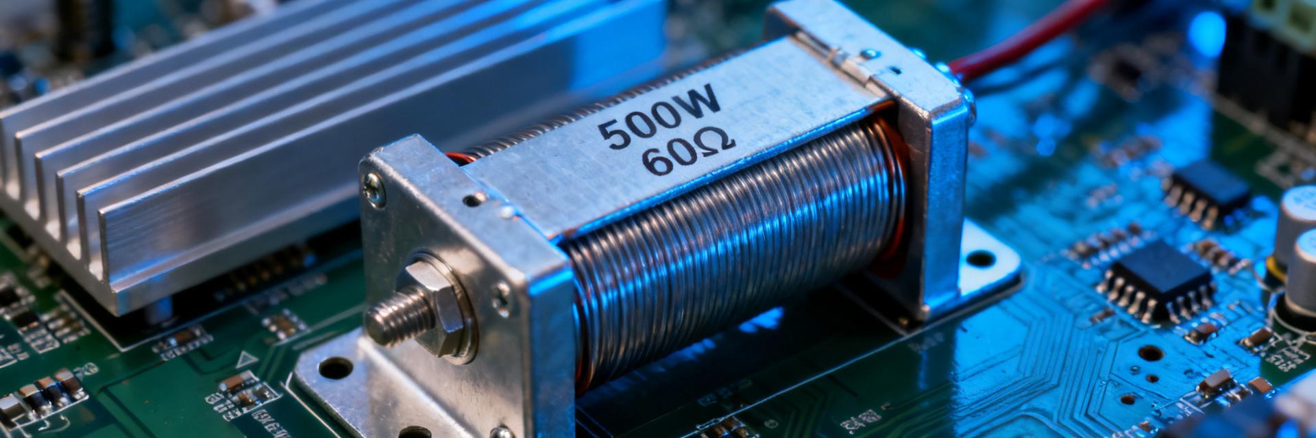
ULV Series Positioning and Package Characteristics
The ULV series belongs to aluminum housed wirewound power resistors, utilizing a thermally conductive cement filling and aluminum alloy housing structure, offering a standard operating temperature range of -55°C to +200°C at the 500W power rating. Compared to the ULH series, the ULV offers superior short-time overload capability at the same power level—typically up to 2x rated power for 5 seconds. This characteristic makes it highly outstanding in servo motor braking and variable frequency drive (VFD) discharge circuits. What you need to focus on is not just the static power, but also the thermal capacity advantage provided by its packaging.
Parameter-by-Parameter Breakdown: Meaning of N, 60J, FL=500
- N: Represents a non-inductive design, which is particularly suitable for high-frequency switching circuits to reduce the impact of parasitic inductance on waveforms. If your application involves IGBT or SiC devices, this is a critical consideration.
- 60J: Nominal resistance of 60Ω, where J represents a ±5% resistance tolerance. For braking resistor applications, this tolerance range fully satisfies energy dissipation control requirements.
- FL=500: Lead wire length is 500mm, facilitating flexible installation and layout inside cabinets or equipment. The long lead design also provides you with more generous wiring clearance.
In-Depth Analysis of Key Performance Parameters
Relationship Between Rated Power and Thermal Dissipation Conditions
The 500W rated power of the ULV 500 N 60 J FL=500 is based on the assumption of a case temperature ≤25°C. In practical applications, when the ambient temperature rises to 70°C, the power must be limited to approximately 350W according to the derating curve. During selection, it is crucial to verify the ventilation conditions at the installation site or if auxiliary cooling measures are required. For instance, in an enclosed electrical cabinet without forced air cooling, it is recommended to reserve at least a 20% power margin to prevent long-term high temperatures from accelerating insulation aging.
Instantaneous Voltage Rating and Pulse Load Capability
This model features a 750V instantaneous voltage rating. Paired with a 60Ω resistance, the calculated maximum peak current is 12.5A. Within a typical 60-second cycle, the resistor temperature rise is controlled to ≤175K, meaning it can withstand periodic pulse loads without affecting long-term reliability. You can refer to this curve to evaluate compatibility with short-time braking or discharging conditions. If your system requires frequent start-stops, be sure to verify the pulse energy and time product to ensure it does not exceed the I²t rating.
Temperature Coefficient and Long-Term Stability
The temperature coefficient of resistance (TCR) of 260ppm/°C is mid-range for power resistors, meaning that under a 100°C temperature rise, the maximum resistance shift is about ±15.6%. For non-precision applications like braking resistors, this deviation does not affect functionality; however, if used for current sensing, a precision model with a lower TCR must be selected. Long-term stability tests show that after 1000 hours of operation at rated load, the resistance change rate is typically less than 1%, ensuring consistent performance of your equipment throughout its life cycle.
Typical Application Scenarios and Selection Comparison
Servo Drive Braking Resistor: Matching Scenarios for ULV 500 N 60 J
In 5kW to 7.5kW servo systems, the 60Ω resistance of the ULV 500 N 60 J FL=500 matches the dynamic braking requirements of a 380V bus voltage. Calculating peak braking power: based on P=U²/R, a 380V DC bus corresponds to a power of approximately 2400W (well above the rated value). However, thanks to its pulse capability within a 60-second cycle, this resistor can safely absorb short-time regenerative energy. During selection, confirm that the braking duty cycle does not exceed the rated curve range. For example, a typical vertical machining center spindle braking cycle of 10 seconds deceleration + 50 seconds idle falls perfectly within the safe operating area.
Comparison with ULV 500 100 J (100Ω Version)
| Parameter | ULV 500 N 60 J | ULV 500 100 J |
|---|---|---|
| Resistance Value | 60Ω | 100Ω |
| Peak Current @ 750V | 12.5A | 7.5A |
| Compatible Motor Power | 5-7.5kW (380V System) | 7.5-11kW (Higher Bus Voltage) |
| Braking Torque Characteristics | Faster energy absorption | Smoother torque control |
Choosing between 60Ω and 100Ω depends primarily on the bus voltage level and the required braking torque curve. At the same voltage, 60Ω can absorb higher power, making it suitable for operating conditions requiring fast stops; 100Ω is better suited for scenarios requiring precise control over the deceleration curve. You can simulate the torque response under both resistance values using dynamic simulation software to visualize and confirm the differences.
Installation Methods and Thermal Design Key Points
The FL=500 lead wire design supports panel mounting or independent bracket fixing. The bottom of the aluminum housing must make full contact with the heat dissipation surface; it is recommended to apply thermal grease and control the flatness of the contact surface to within 0.05mm. Under natural convection conditions, the case temperature can reach the 200°C upper limit at 500W full load. A minimum of 20% derating is recommended to extend service life. In actual installations, if vertical mounting is used and there are surrounding obstructions, the heat dissipation efficiency will drop by about 15%, which must be included in calculations.
Selection Decision Checklist: 5 Steps to Confirm if ULV 500 N 60 J FL=500 is Suitable
Electrical Parameter Verification
- Peak Power Calculation: Confirm the maximum instantaneous power and duration under braking or discharge conditions. Use an oscilloscope to measure actual bus voltage fluctuations rather than relying solely on theoretical values.
- Duty Cycle Matching: Compare the actual pulse cycle with the 60-second temperature rise curve to ensure the temperature rise is ≤175K. If your cycle is shorter than 60 seconds, calculate based on equivalent power.
- Voltage Margin: Confirm that the maximum transient voltage of the system does not exceed 750V. Considering grid fluctuations combined with harmonics, a 10% safety margin is recommended.
Thermal Management Confirmation
- Thermal Path Design: Confirm that the installation location has sufficient heat dissipation area or forced air cooling conditions. Calculate thermal resistance: Rth=(Tmax-Tamb)/Pdiss, to ensure the aluminum case temperature is below 200°C.
- Derating Allowance: Under maximum ambient temperature, ensure the actual power does not exceed 70-80% of the rated value. If the ambient temperature can reach 50°C, it is recommended to limit the maximum continuous power to 400W.
Summary
- ULV 500 N 60 J FL=500, as a 500W-class aluminum housed wirewound power resistor, delivers core value in the balance between its 60Ω resistance and high pulse tolerance—making it a reliable choice for 5-7.5kW servo braking and VFD discharge circuits.
- The key to selection lies in: verifying whether the pulse load curve matches, confirming whether heat dissipation conditions are adequate, and maintaining an appropriate derating margin. Neglecting any of these aspects may lead to early failure.
- When these conditions are met, this model will provide a stable service life of over 100,000 cycles, serving as a trustworthy "energy buffer" in your power system. In your 2025 design cycle, including the ULV 500 N 60 J in your BOM will add a reliable safety barrier to your power circuit.
FAQs about ULV 500 N 60 J FL=500
What is the maximum operating temperature of the ULV 500 N 60 J FL=500?
The maximum operating temperature for this model is +200°C (case temperature). At this temperature, the resistor's insulation material and wirewound structure still maintain stable electrical performance, but you will notice that the resistance value has shifted by approximately ±15.6%. To extend service life, it is recommended to keep the continuous operating temperature below 150°C, with the upper limit allowed only under short-time pulse conditions.
How do I determine if the ULV 500 N 60 J is compatible with my 380V servo system?
First, calculate the braking energy: E=0.5*J*(ω1²-ω2²), where J is the load inertia and ω is the angular velocity. Then, compare whether the average power within a 60-second cycle is below 500W and ensure the peak power does not exceed the pulse curve. For a typical 5kW servo with a 3-second deceleration time and a 5% duty cycle, this model is fully capable.
What specific advantages does the non-inductive design of the ULV 500 N 60 J offer?
The non-inductive (N) design reduces parasitic inductance to an extremely low level (typically less than 1μH), which is critical for high-frequency switching circuits. In IGBT or SiC inverters, low inductance significantly reduces voltage spikes during turn-off and lowers electromagnetic interference (EMI). If your system's switching frequency exceeds 10kHz, this characteristic is particularly important.
How does the lead wire length of FL=500 affect installation?
The 500mm lead wires provide additional installation flexibility, allowing the resistor body to be placed away from the terminal blocks to facilitate thermal layout. However, please note that long leads may introduce tiny inductances at ultra-high frequencies, which requires extra consideration for RF applications. At standard industrial frequencies (50/60Hz), the impact is completely negligible.


