

In variable frequency drive (VFD) braking systems, if the thermal design of a 400W power-rated braking resistor is improper, the actual usable power may plummet to below 30% of its nominal value. As a core device in industrial braking scenarios, the thermal performance of the ULV400-200Ω directly determines the system's safety margin. Based on measured data and engineering cases, this article deconstructs the complete technical blueprint of this model under 400W operating conditions—from heat dissipation mechanisms to derating strategies—providing quantifiable decision-making bases for selection and application.
Core Parameters and Structural Analysis of the ULV400-200Ω
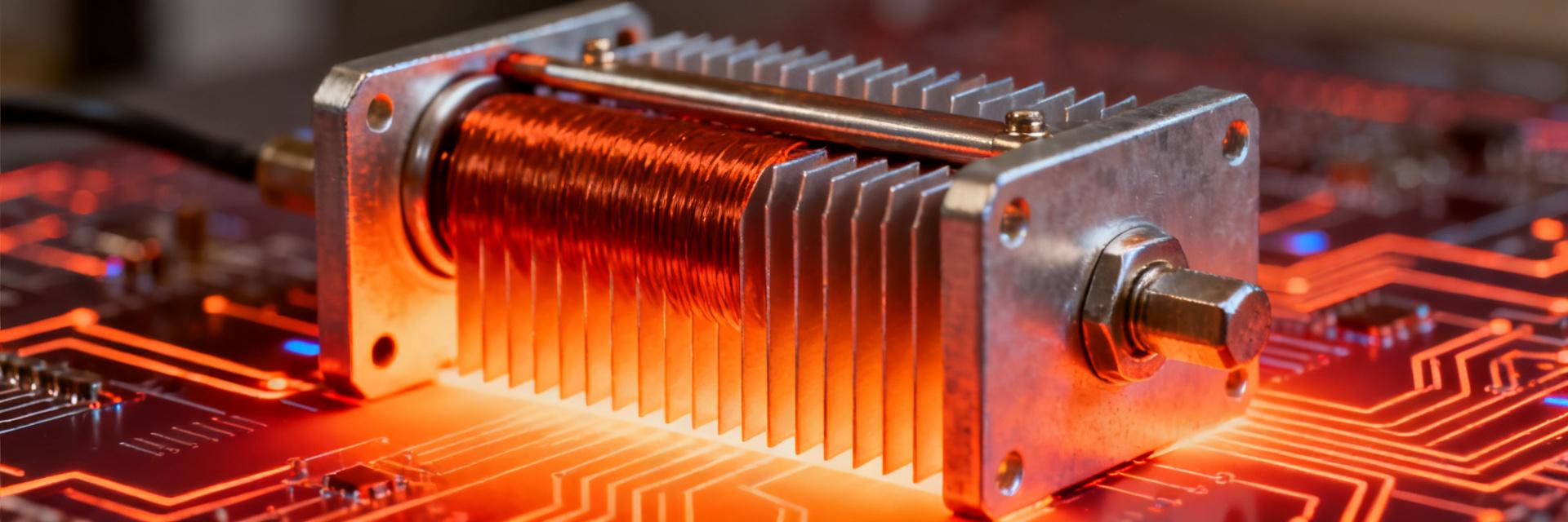
The nomenclature of the ULV400-200Ω contains key technical indicators: 400 represents the rated power of 400W, 200Ω is the nominal resistance, and the ULV series points to an aluminum-clad, high-power-density design. This model utilizes a metal oxide film resistor core, with the temperature coefficient of resistance (TCR) controlled within ±250ppm/°C to ensure resistance stability under high-temperature operating conditions.
Electrical Specifications Overview: Resistance Accuracy, Power Rating, and Dielectric Withstand Characteristics
The tolerance class of the nominal 200Ω resistance is typically ±5% (J class), with custom versions reaching up to ±1%. The 400W rated power is defined based on a 40°C ambient temperature and standard mounting conditions, with a dielectric withstand voltage of no less than AC2500V/1min. The insulation resistance must be greater than 100MΩ at room temperature and remain above 10MΩ after damp heat testing. These parameters collectively constitute the electrical safety baseline of the device.
| Key Parameter | Technical Indicator / Specification Standard | Test Condition / Description |
|---|---|---|
| Rated Power (P_rated) | 400 W | Based on 40°C ambient temperature and standard flat mounting |
| Nominal Resistance (R_nominal) | 200 Ω | Tolerance class ±5% (J class) / Customizable to ±1% (F class) |
| Temperature Coefficient of Resistance (TCR) | ±250 ppm/℃ | Operating temperature range: -55℃ to +200℃ |
| Dielectric Withstand Voltage | AC 2500 V / 1 min | Leakage current < 0.5mA, between terminals and aluminum housing |
| Insulation Resistance | > 100 MΩ (room temp) / > 10 MΩ (damp heat) | Test voltage DC 500V |
| Typical Thermal Resistance (Rth_internal) | Approx. 0.8 ℃/W | Conduction thermal resistance from internal resistor core to outer aluminum housing surface |
Packaging Architecture: Collaborative Design of Aluminum Housing Heatsink and Ceramic Insulation Layer
The aluminum housing serves dual functions of heat dissipation and shielding, with its surface anodized to form an insulating layer that withstands up to DC2500V. The internal resistor core is coupled to the housing via a highly thermally conductive ceramic substrate, with a typical thermal resistance of approximately 0.8°C/W. This "core-substrate-housing" three-stage structure rapidly conducts Joule heat outward while maintaining electrical isolation. Thermal grease must be applied to the mounting surface to reduce contact thermal resistance; otherwise, the measured temperature rise may increase by 15-20K.
Heat Generation Mechanism and Heat Dissipation Paths under 400W Power
The essence of a braking resistor is to convert regenerative electrical energy into thermal energy. When the VFD drives the motor to decelerate, the motor enters a generating state, causing the DC bus voltage to pump up. Once the braking unit conducts, it discharges energy to the resistor. A continuous power of 400W means 400 Joules of heat are generated per second. If this heat accumulates without dissipating, the temperature rise will deteriorate exponentially.
Joule Heat Calculation: Braking Energy Conversion and Transient Temperature Rise Model
Braking power is P=V²/R, where V is the turn-on threshold of the braking unit (typically DC700-750V). Calculated with a 200Ω resistance, the peak current is approximately 3.5A, and the transient power can reach up to 2.5kW—far exceeding the 400W rated value. Therefore, braking resistor design follows the principle of "short-time overload, average power limiting". The thermal capacity model simplifies the resistor core as a lumped thermal capacity Cth, where the temperature rise ΔT=P×t/Cth, and t is the braking duration. The thermal time constant of a typical aluminum-clad resistor is about 5-10 minutes, and its short-time overload capability can reach up to 10 times the rated power (<10s).
Thermal Resistance Network Analysis: Three-stage Conduction from Resistor Core to Ambient Air
The complete thermal path includes: core → ceramic substrate (thermal resistance Rth1 ≈ 0.3°C/W) → aluminum housing (Rth2 ≈ 0.5°C/W) → heatsink/ambient (variable Rth3). The total thermal resistance Rth = Rth1 + Rth2 + Rth3 determines the steady-state temperature rise ΔT = P × Rth. If Rth3 increases from 2°C/W to 5°C/W due to poor installation, the temperature rise under 400W operating conditions will soar from 1000°C to over 2000°C—far exceeding material limits. This explains why the lifespan of the same model can vary by dozens of times under different heat dissipation conditions.
Forced-Air Cooling vs. Natural Convection: Performance Comparison of Two Cooling Modes
Under natural convection conditions, the usable power of the ULV400-200Ω must be derated by 60-70%, meaning the recommended actual continuous load should not exceed 240-280W. Forced-air cooling (wind speed of 3-5m/s) can reduce the thermal resistance Rth3 by more than 50%, making 400W full-power operation possible. Measured data shows that without forced cooling, the steady-state housing temperature is about 180°C; after installing an axial fan, it can be controlled within 120°C, correspondingly dropping the resistor core temperature from 280°C to below 200°C, which extends the lifespan by 3 to 5 times.
Detailed Explanation of Derating Curves: Three-Dimensional Constraints of Temperature, Altitude, and Duty Cycle
The derating curve is the core basis for braking resistor selection, revealing the non-linear relationship between power capability and boundary conditions. The derating characteristics of the ULV400-200Ω need to be comprehensively interpreted from three dimensions.
Standard Derating Curve: Power Attenuation Law from Ambient Temperature of 40°C to 150°C
Taking 40°C as the reference point (100% power), for every 10°C increase in ambient temperature, the usable power decreases by approximately 8-10%. At 100°C, the power drops to around 60%, and at 150°C, only 30-40% remains. This attenuation stems from the dual constraints of accelerated insulation material aging and thermal stress accumulation in the resistive film. The curve exhibits a convex downward shape, with a steeper slope in the high-temperature zone, indicating that the safety margin near the critical temperature must be exceptionally conservative.
Special Operating Condition Correction: Superimposed Effects of High Altitude/Low Air Pressure and High-Frequency Braking Pulses
When the altitude exceeds 2000m, the decrease in air pressure leads to a decline in convective heat dissipation efficiency, requiring an additional derating of 10-15%. The cyclic thermal stress introduced by high-frequency braking pulses (such as frequent elevator start-stops) makes the equivalent aging rate higher than under steady-state conditions, suggesting a conversion using a safety factor of 1.5-2 times. When multiple factors are superimposed, multiplicative correction is applied: Actual Usable Power = Rated Power × Temperature Coefficient × Altitude Coefficient × Duty Cycle Coefficient.
Thermal Design Practice: From Theory to Engineering Implementation
Theoretical calculations must be transformed into executable engineering specifications; the following key points directly determine the success or failure of the thermal design.
Heatsink Selection Formula: Thermal Resistance Matching and Surface Area Calculation
The required heatsink thermal resistance is Rth_sink = (Tmax - Tambient) / P - Rth_internal. Assuming the maximum allowable temperature of the resistor core is 250°C, the ambient temperature is 50°C, the power is 400W, and the internal thermal resistance is 1.3°C/W, then Rth_sink must be ≤ (250 - 50) / 400 - 1.3 = 0.2°C/W. Estimating extruded aluminum heatsinks at 0.05-0.1°C/W per square centimeter, an effective heat dissipation area of 2000-4000 cm² is required, or forced-air cooling must be adopted to reduce physical volume.
Installation Layout Taboos: Spacing Requirements, Airflow Direction, and Thermal Isolation Strategies
The minimum spacing between resistors should be ≥ 50mm to avoid mutual interference of thermal plumes; the temperature difference between the air inlet and outlet should be controlled within 15°C to prevent localized overheating; heat-sensitive components (electrolytic capacitors, optocouplers) must be kept more than 300mm away from the resistor or provided with thermal insulation barriers. Vertical installation favors the chimney effect, while horizontal installation must ensure airflow penetrates from bottom to top.
Typical Application Scenarios and Fault Avoidance Guide
The ULV400-200Ω is widely used in potential energy load scenarios such as hoisting machinery, elevators, and centrifuges. The following example reveals common design pitfalls.
VFD Braking System: Parameter Configuration Examples for Elevators and Hoisting Machinery
A certain 3.7kW elevator VFD is equipped with the ULV400-200Ω, and the braking unit threshold is set to DC720V. The measured peak braking current is 3.6A, and the single braking energy is about 5000J. Calculated based on 120 braking cycles per hour and a 10% duty cycle, the equivalent average power is approximately 167W, which is far below the 400W rated value; however, the transient temperature rise still needs to be verified. It is recommended to configure a temperature switch (normally closed, 120°C) connected in series with the control loop to achieve hardware-level protection.
Overtemperature Failure Early Warning: Infrared Temperature Measurement Point Setup and Protection Circuit Design
For infrared temperature measurement, priority should be given to selecting the center point of the aluminum housing surface, with the emissivity set to 0.85-0.95. The protection circuit is recommended to have a three-stage architecture: temperature switch (hardware) → thermistor + comparator (hardware fast response) → MCU temperature model (software warning). The response time gradient is: temperature switch <100ms, comparator circuit <10ms, and software warning can predict the trend several seconds in advance.
Key Takeaways
- Thermal Resistance Dominates Design: The 400W rated power of the ULV400-200Ω is highly dependent on heat dissipation conditions; for every 1°C/W increase in mounting thermal resistance, the usable power decreases by approximately 25%
- Non-linear Derating Characteristics: Power attenuation accelerates when the ambient temperature exceeds 100°C; high-temperature scenarios require a safety margin of over 50%
- Necessity of Forced-Air Cooling: Natural convection only supports a 240-280W continuous load; full-power operation must be configured with a wind speed of 3m/s or higher
- Multi-factor Superimposed Correction: Altitude, duty cycle, and pulse frequency must be multiplicatively superimposed for derating to avoid overheating risks caused by single-factor evaluation
- Three-stage Protection Architecture: A hardware temperature switch + comparator + software model constitute a complete thermal protection system, with response times covering from ms to min scales
FAQ
Is forced-air cooling mandatory for the ULV400-200Ω at 400W power?
It depends on the ambient temperature and installation conditions. Under a 40°C environment, natural convection only supports a continuous load of approximately 240W. If full-power operation is required or the ambient temperature exceeds 60°C, forced-air cooling is a necessary configuration. It is recommended to verify via measured housing temperature: the aluminum housing surface should not exceed 120°C during steady-state operation; otherwise, heat dissipation must be enhanced.
How to determine if the braking resistor is undersized?
Observe three symptoms: the DC bus voltage continuously climbs to the overvoltage threshold during braking; the resistor housing discolors or the paint layer blisters; the VFD frequently reports braking resistor overtemperature faults. The quantitative method is to record the braking duty cycle. If the calculated average power exceeds 80% of the usable value after derating, it is recommended to upgrade the model or improve heat dissipation.
What special measures are required when using the ULV400-200Ω in high-altitude areas?
An additional derating of 10-15% is required above 2000m altitude, and 20% is recommended above 3000m. Priority should be given to forced-air cooling to compensate for the loss of convection efficiency, while shortening the maintenance cycle and focusing on checking for signs of insulation aging. If conditions permit, selecting a high-altitude dedicated model with a vacuum varnishing process is more reliable.
How to predict and extend the lifespan of a braking resistor?
Lifespan mainly depends on the maximum temperature of the resistor core and the number of cycles. For every 10°C decrease in temperature, the lifespan is approximately doubled. Key measures to extend lifespan include: optimizing the braking unit threshold to reduce unnecessary braking; increasing heat dissipation capacity to reduce steady-state temperature rise; and avoiding cyclic thermal fatigue caused by high-frequency, low-energy braking.


