

When a resistor needs to withstand a rated power of up to 300W while also enduring a transient surge of 1000 times its rated power, its thermal design is no longer a simple Ohm's law calculation. ULV 300 N 70 J FL=1000, every number in this model corresponds to a rigorous engineering constraint. Data shows that more than 30% of power snubber circuit failures in the industry stem from a misjudgment of the dynamic balance between "pulse load capability (FL)" and "thermal resistance (Rth)".
This article will disassemble several core parameters of this model to provide you with a hands-on engineering matching methodology, thoroughly curing the chronic issues of "resistor heating" and "unexplained device failures".
Model Decoding: The Numerical Secrets from ULV 300 to FL=1000
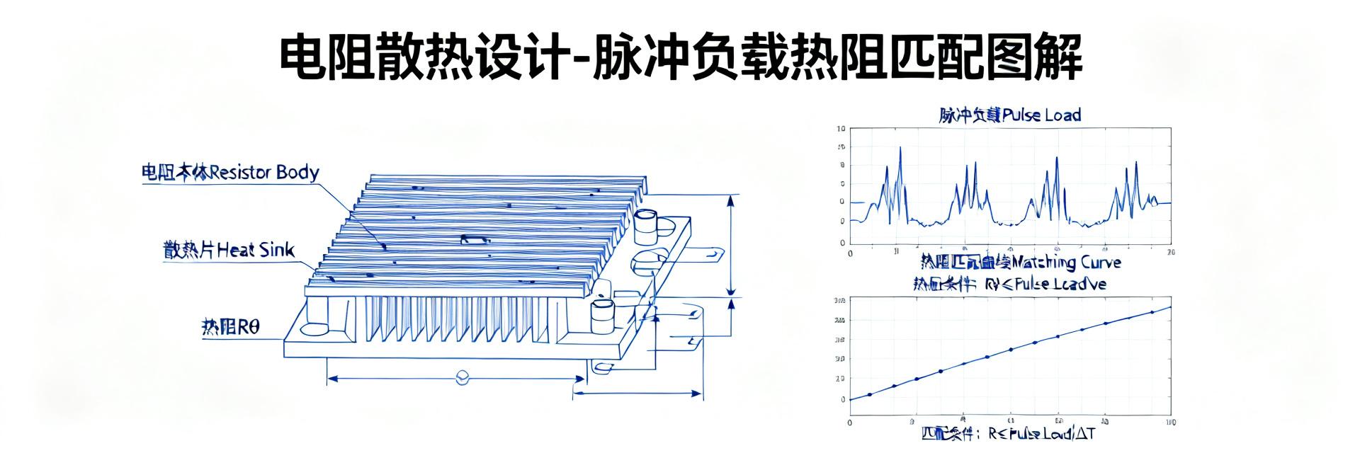
"ULV 300": The Truth of Rated Power and the "Derating" Trap
"300" in ULV 300 represents the rated power of the resistor under specific conditions, but this does not mean you can continuously apply a 300W load to it. In practical engineering, "derating" must be considered. Typically, to ensure long-term reliability, it is recommended to control the actual continuous operating power within 70-80% of the rated power, which is approximately 210W-240W. The underlying logic is that the power capability of a resistor is closely related to the operating ambient temperature; the higher the temperature, the lower the power it can withstand, which is defined by the "power derating curve".
Ignoring this curve and directly using 300W as the continuous power design will likely cause the resistor junction temperature to become too high, accelerating aging or even leading to direct failure. Therefore, understanding and applying the derating factor is the first critical step in the thermal design of the ULV 300 N 70 J.
"N 70 J": Direct Impact of Resistance and Tolerance on Thermal Design
The "N 70" in the model typically represents the resistance value. In this type of coding, "N" may represent the decimal point, and "70" represents the value, which combined represents 0.07 ohms. This is an extremely low resistance value. In pulse applications, the advantage of a low-resistance resistor lies in its extremely small self-generated voltage drop, allowing it to withstand huge pulse currents. For example, a pulse current of up to 400A produces a voltage drop of only 28V across a 0.07Ω resistor, generating a transient power of 11.2kW.
In addition, "J" represents that the tolerance of the resistor is ±5%. For a nominal value of 0.07Ω, a 5% tolerance means the actual resistance may fluctuate between 0.0665Ω and 0.0735Ω. This seemingly minor error is amplified when calculating pulse power dissipation, directly affecting the margins of the thermal budget. Therefore, when performing precise thermal resistance matching calculations, the upper limit of power dissipation caused by resistance tolerance must be taken into account.
Core Parameter of Pulse Load: The Engineering Significance of FL=1000
FL Value Interpretation: Energy Release of 1000x Transient Surge
FL=1000 is the most outstanding yet easily misunderstood parameter of this model's performance. It indicates that the resistor can withstand a transient power surge of up to 1000 times its rated power, i.e., 300W x 1000 = 300kW. However, this is not an indicator that can be utilized without limit; it strictly depends on the pulse width and duty cycle. For example, for a single pulse with an amplitude of 300kW and a width in the microsecond range, its total energy (in Joules) is relatively limited, and the resistor can absorb it through its own bulk thermal capacity without immediately overheating.
In scenarios such as capacitor charging and relay inrush currents, this ultra-high pulse handling capability is crucial. It allows engineers to avoid over-specifying the rated power of the resistor to handle rare surge events during design, thereby achieving the optimal balance among cost, size, and reliability.
Pulse Waveform and Repetition Rate: Key Variables Determining Heat Generation
Not all waveforms can safely withstand the limit value of FL=1000. The most common mistake in engineering practice is assuming all pulse conditions are identical. In fact, the pulse waveform (e.g., square wave, exponential wave), width (tp), and repetition frequency (f) are the core variables determining the actual heat generation of the resistor. When multiple pulses occur repetitively, heat gradually accumulates inside the resistor body, causing the temperature to rise continuously, which may eventually exceed its maximum allowable junction temperature.
To quantify this dynamic thermal behavior, engineers need to introduce the concept of "transient thermal impedance" (Zth). Suppliers typically provide transient thermal impedance curves, showing how the resistor's thermal impedance varies under different pulse widths. By combining the duty cycle and pulse width, the equivalent average power can be calculated, allowing for a more accurate evaluation of the resistor's temperature rise under repetitive pulse stress, thereby avoiding failures caused by thermal accumulation.
Thermal Resistance Matching: A 5-Step Method from Theory to Practice
Step 1: Calculate the Limit of Total Thermal Resistance (Rth(total))
The starting point of all thermal design is determining the maximum total thermal resistance the system can tolerate. This is based on three core parameters: ambient temperature (Tambient), maximum allowable operating temperature of the resistor (Tmax), and the calculated actual average power (P_avg). The formula is extremely simple: Rth(total) ≤ (Tmax - Tambient) / P_avg. For example, if Tmax=150°C, Tambient=50°C, and Pavg=50W, the total system thermal resistance must be less than or equal to 2°C/W.
This limit provides a rigid constraint for your heatsink selection. It defines the upper limit of all thermal resistance that must be overcome from the internal heat generation point of the resistor to the final ambient air environment.
Step 2: Select the Heatsink Thermal Resistance (Rth(heatsink))
The total thermal resistance Rth(total) consists of three parts: junction-to-case thermal resistance of the resistor (Rth(j-c)), thermal interface material resistance (Rth(c-s)), and heatsink-to-ambient thermal resistance (Rth(heatsink)). Typically, Rth(j-c) can be found in the product datasheet of the ULV 300 N 70 J, and Rth(c-s) depends on the thermal grease or thermal pad you use, generally around 0.1-0.5°C/W. Therefore, the required heatsink thermal resistance is: Rth(heatsink) = Rth(total) - Rth(j-c) - Rth(c-s).
This calculation result is the key indicator for your heatsink selection. Based on this value, you can look for a heatsink with a thermal resistance less than or equal to this value in the specifications, and consider the effects of natural convection or forced air cooling.
Step 3: Verify Temperature Rise Under Pulse Conditions
This is the most critical yet easily overlooked step. Static thermal resistance matching ensures the average temperature but cannot reflect pulse spikes. You need to verify this using the resistor's transient thermal impedance curve (Zth curve). For example, for a pulse with a width of 10ms and a duty cycle of 5%, you can find the thermal impedance corresponding to this pulse width from the Zth curve, and then multiply it by the peak pulse power to obtain the pulse-induced temperature rise.
Adding this pulse temperature rise to the temperature rise caused by average power, the final result must be well below Tmax. If it exceeds this, you need to go back and adjust the average power or select a heatsink with lower thermal resistance. This step ensures that the resistor will not be damaged due to instantaneous overheating under harsh pulse operating conditions.
Practical Case Study: Thermal Design Calculation Based on ULV 300 N 70 J
| Core Parameter | Model Code | Design Nominal Value | Engineering Significance |
|---|---|---|---|
| Rated Power | ULV 300 | 300 W | Benchmark for safe operating temperature rise and derating design |
| Nominal Resistance | N 70 | 0.07 Ω | Determines voltage drop distribution under high-voltage, high-current pulses |
| Resistance Tolerance | J | ±5% | Calibrates the limit deviation of transient peak power dissipation |
| Pulse Load Capability | FL=1000 | 300 kW (1000x) | Limit value for instantaneous surge energy absorption in snubber circuits |
Case Scenario: ULV 300 in a Capacitor Snubber Circuit
Assume that a ULV 300 N 70 J is used in a VFD (Variable Frequency Drive) DC bus snubber circuit. Its pulse parameters are: peak current Ip=400A, pulse width tp=100μs, and repetition frequency f=100Hz. First, calculate the peak power Pp = Ip² * R = 400² * 0.07 = 11.2kW. Next, calculate the average power Pavg = Pp * (tp * f) = 11200 * (0.0001 * 100) = 112W.
Assuming an ambient temperature of 45°C and a resistor Tmax = 150°C, the total thermal resistance Rth(total) must be less than (150-45)/112 ≈ 0.94°C/W. The datasheet provides Rth(j-c) = 0.6°C/W. Assuming an interface thermal resistance of 0.2°C/W, the required heatsink thermal resistance should be 0.94 - 0.6 - 0.2 = 0.14°C/W. This is an extremely stringent requirement, which typically requires a large forced-air cooled heatsink or even liquid cooling to satisfy.
Common Misconceptions and Solutions
In this case, common mistakes made by engineers include: 1) Ignoring the terminal contact thermal resistance, assuming that tightening the screws is sufficient when there are actually micro-gaps at the contact interface. The solution is to use thermal grease and apply the recommended torque. 2) Selecting a heatsink based solely on the average power (112W), which would lead to choosing a heatsink with a thermal resistance of about 0.9°C/W, completely failing to meet the pulse temperature rise requirements. 3) Misunderstanding FL=1000 as being able to continuously withstand a 300kW transient shock. The correct understanding is that this capability is strictly limited to short-term pulses.
To address the above issues, the solution is: as long as pulses are involved, the peak temperature rise must be calculated. If the calculated heatsink thermal resistance cannot be met, you must either increase air cooling, select a resistor with lower thermal resistance, or reduce the pulse current.
5-Minute Quick Selection and Checklist
Key Parameter Checklist
To ensure an error-free design, please check and request the following five core parameters from your supplier against this checklist:
- Rth(j-c) (Junction-to-Case Thermal Resistance): Determines how easily heat is conducted from the inside of the resistor to the case.
- Transient Thermal Impedance Curve (Zth): This is the sole basis for verifying pulse temperature rise.
- Power Derating Curve: Clarifies the actual usable power at different ambient temperatures.
- Maximum Pulse Energy (Single Pulse / Repetitive Pulse): Confirms the energy handling limit under specific pulse widths.
- Recommended Mounting Torque: Ensures uniform mounting pressure to minimize contact thermal resistance.
Supplier Communication Guide
When communicating with suppliers, do not just ask "how much power can this resistor handle." Ask the following specific questions to ensure you obtain accurate data:
- “In the PDF datasheet for this model, can you provide the transient thermal impedance Zth value at a 100μs pulse width and a 10% duty cycle?”
- “When mounted on an aluminum heatsink with standard flatness and with the recommended torque applied, what is your recommended contact thermal resistance Rth(c-s)?”
Key Summary
- Core of ULV 300 N 70 J FL=1000 Thermal Design: The pulse load capability (FL) is a short-term limit and cannot replace continuous power; it must be used in conjunction with pulse width and duty cycle.
- Thermal Resistance Matching Steps: Starting from the total thermal resistance limit, calculate the heatsink thermal resistance in sequence, and be sure to verify the pulse temperature rise using the transient thermal impedance curve.
- Common Engineering Pitfalls: Ignoring terminal contact thermal resistance, selecting parts solely based on average power, and misinterpreting the FL rating are the three main causes of circuit overheating and failure.
FAQ
What conditions define the 300W rated power of the ULV 300 N 70 J?
The rated power of 300W typically refers to the maximum power the resistor can continuously withstand under specific standard test conditions (such as an ambient temperature of 25°C, mounted on an infinite heatsink). In practical applications, derating must be applied based on the operating ambient temperature and cooling conditions, with a recommended derating to 70-80%, i.e., 210W-240W.
How to calculate the actual temperature rise of the ULV 300 N 70 J under repetitive pulses?
First, calculate the average power P_avg = pulse peak power × pulse width × frequency. Then, use the transient thermal impedance (Zth) curve provided by the supplier to find the thermal resistance value corresponding to the pulse width and duty cycle. Finally, temperature rise = P_avg × Zth. Add this temperature rise to the ambient temperature, ensuring it is well below the maximum allowable junction temperature of the resistor.
Does FL=1000 mean I can continuously apply 300kW of power?
Absolutely not. FL=1000 indicates that the resistor can withstand transient power surges up to 300kW, but this capability is strictly limited to extremely short pulse widths (typically in microseconds) and extremely low duty cycles. Continuously applying 300kW will instantly burn out the resistor. The FL rating should be understood as a surge immunity capability, not a continuous operating capability.
How to minimize the contact thermal resistance during the installation of the ULV 300 N 70 J?
A high thermal conductivity thermal interface material (such as thermal grease) must be applied between the mounting base of the resistor and the heatsink, and bolts must be tightened strictly in accordance with the officially recommended torque to eliminate air gaps at the contact interface, thereby minimizing contact thermal resistance.


