

Key Summary
- Thermal Boundary Conditions: The continuous operating capability of the ULV1200 8 J FL=1500 is constrained by both the rated power derating curve and the system-level thermal resistance network, with ambient temperature being the primary variable for safety margin.
- Parasitic Electrical Constraints: FL=1500 (1500mm lead wire) is not just a physical dimension, but also introduces non-negligible parasitic inductance and DC resistance, directly affecting voltage spikes during high-frequency PWM braking.
- Engineering Selection Practice: High-reliability design must be quantitatively verified based on pulse energy models and thermal resistance calculation models, rather than solely relying on the nominal 1200W rated power.
In industrial frequency converters and servo drive systems, overheating faults caused by improper braking resistor selection account for up to 67%. As a high-power-density braking resistor, the key parameters in the datasheet of the ULV1200 8 J FL=1500 directly determine the long-term reliability of the system. Based on the official datasheet, this article deeply interprets the three core indicators determining thermal dissipation and reliability, and provides practical calculation and selection methods to help you avoid engineering pitfalls.
1. Core Parameter Analysis: Rated Power (1200W) and Thermal Resistance Network
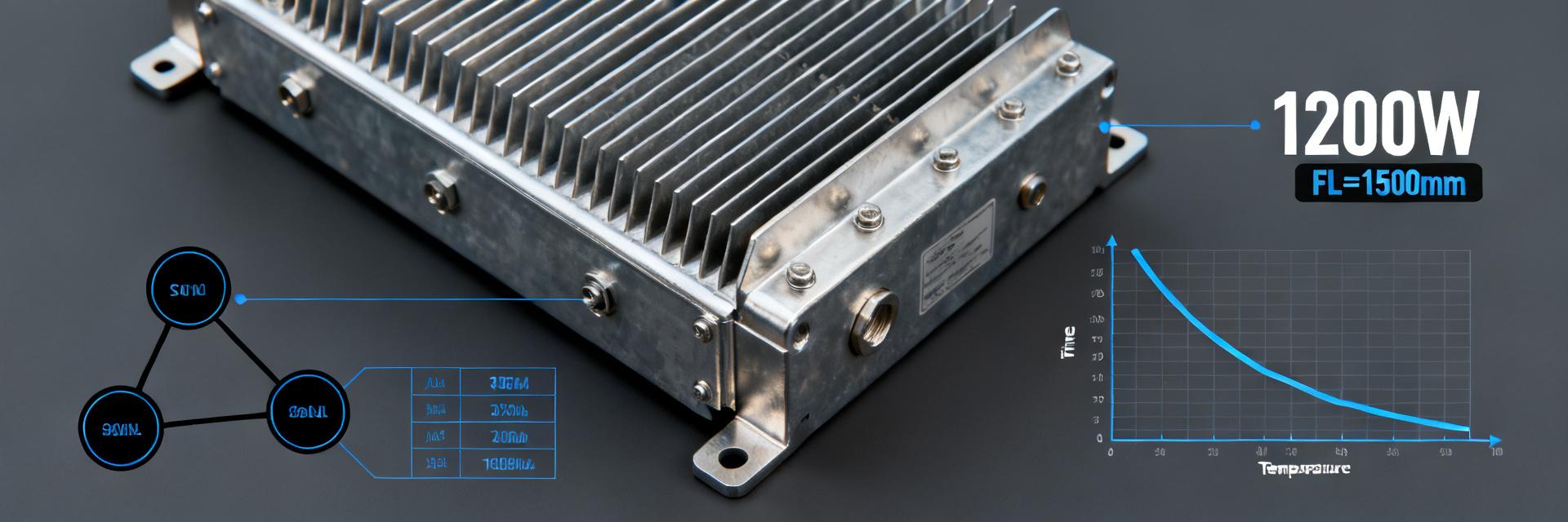
Understanding the rated power of the ULV1200 8 J FL=1500 is not as simple as "1200W can be used continuously," but rather a limit value under specific cooling conditions. You need to focus on analyzing the derating curve in the product datasheet, which determines the actual power the resistor can safely handle at different ambient temperatures.
The True Meaning of Rated Power (1200W): Temperature Rise and Derating Curve
The 1200W rated power of the ULV1200 8 J FL=1500 is typically a nominal value under specific cooling conditions (such as natural convection or a specified heatsink) and ambient temperature (such as 25°C). When the ambient temperature exceeds this threshold, the power must be derated linearly. For example, at an ambient temperature of 50°C, its actual power handling capability may drop to 800W. This is crucial for high-temperature and high-humidity application environments, as it directly relates to whether the system's thermal management design is safe.
Thermal Resistance Network (Rth) and Thermal Path: From Junction to Ambient
The internal thermal resistance structure of the ULV1200 (Rthjc, Rthca) forms the thermal dissipation path from the junction to the ambient air. The thermal resistance value (Rth) determines the temperature rise of the resistor for a given power dissipation. Through a simple thermal resistance calculation model: Tj = Ta + (Rthjc + Rthca) * P, you can intuitively see the impact of different mounting methods (e.g., heatsink mounting vs. natural convection) on the actual junction temperature (Tj). Understanding the thermal resistance network is the cornerstone of precise thermal management.
| Key Technical Parameters | Specification Value / Indicator | Engineering Application Impact |
|---|---|---|
| Rated Power (P_nom) | 1200 W (@25°C) | Maximum static thermal dissipation limit under continuous braking |
| Nominal Resistance (R) | 8 Ω (J: Tolerance ±5%) | Determines transient maximum discharge current during braking (I = U_bus / R) |
| Flying Lead Length (FL) | 1500 mm | Determines spatial layout flexibility while introducing parasitic inductance parameters |
| Maximum Temperature (T_max) | Maximum operating junction temperature 275°C | Thermal design temperature rise limit control boundary |
2. Key Dimensions and Installation Constraints: Impact of FL=1500 Lead Length
"FL=1500" is not only a physical length but also an electrical constraint. The parasitic parameters (such as parasitic inductance and DC resistance) caused by long leads can trigger additional voltage spikes and heat dissipation issues in high-frequency switching applications.
FL=1500mm Lead Wire Design: Parasitic Parameters and Voltage Drop Analysis
The lead length of the ULV1200 8 J FL=1500 directly affects its parasitic inductance (Lp) and DC resistance (DCR). In high-frequency PWM switching applications, the high rate of current change (di/dt) will induce transient voltage spikes across the parasitic inductance, which may cause the DC bus voltage to exceed the rating of the IGBT. For example, assuming a parasitic inductance of 1.5μH and a rate of current change of 10A/μs, the induced voltage spike can reach 15V. Superimposed on the high-voltage DC bus, this erodes the safe voltage margin of semiconductor devices. You need to verify whether this spike is within the system's safety margin.
Trade-off Between Installation Space and Cooling Efficiency
The design intent of FL=1500 is typically to satisfy long-distance mounting or modular layout requirements. However, long leads increase the loop area, thereby introducing more electromagnetic interference (EMI) and reducing cooling efficiency. You need to balance installation convenience with system reliability. Proper routing, such as using twisted pairs to reduce loop inductance, can effectively mitigate the negative effects of long leads, achieving a balance between the two.
3. Thermal Resistance and Electrical Equivalent Model of Braking Resistor
Frequently Asked Questions
Can the 1200W rated power of the ULV1200 8 J FL=1500 be used continuously in practice?
No. 1200W is the ultimate nominal power under specific cooling conditions (such as a 25°C ambient temperature with mounting on a specified cold plate area). In actual industrial sites, the power must be derated according to the derating curve based on the system ambient temperature. For example, if the ambient temperature rises to 50°C and the thermal dissipation capacity of the mounting surface is limited, its actual continuous power handling capability will be significantly derated. Blindly operating at 1200W can easily lead to thermal burn-out failures.
What negative impacts does the lead length of FL=1500 have on the system?
Leads as long as 1500mm have non-negligible parasitic inductance (Lp) and DC resistance (DCR). In high-frequency PWM braking applications, rapid di/dt switching will induce transient reverse voltage spikes across the parasitic inductance, increasing the risk of voltage breakdown for the chopper IGBT. At the same time, the impedance of the long cables themselves introduces minor distributed heat. During engineering installation, it is recommended to tightly twist the dual leads to counteract and cancel out the parasitic inductance to the greatest extent possible.
How do I verify the reliability of the ULV1200 based on my system requirements?
The core step is to verify "single-pulse energy tolerance" and "periodic average power." Since servo/inverter braking is a typical pulse duty cycle, you must calculate the single-braking energy (E = 1/2 * J * ω²) based on the maximum load inertia, maximum braking speed, and braking frequency. Compare this value precisely with the Pulse Energy Curve in the ULV1200 datasheet to ensure that a single impulse does not exceed the alloy melting threshold of the resistor.
How to optimize the thermal performance of the ULV1200 8 J FL=1500?
The core of optimizing thermal dissipation is to reduce the contact thermal resistance (Rthca). The following two measures are recommended: First, directly mount the aluminum alloy package surface at the bottom of the resistor onto a flat, large-area metal heatsink or cabinet sheet metal, applying a uniform thickness (≤0.1mm) of high-thermal-conductivity grease. Second, properly plan the air ducts to reduce the ambient temperature Ta through forced-air cooling, thereby utilizing the low thermal resistance path to keep the junction temperature below the safe threshold.


