

In the power circuit design of industrial power supplies, frequency converters, and new energy equipment, the selection of 300W-class wirewound resistors directly determines system heat dissipation efficiency and long-term reliability. As a typical representative of metal clad packaging, the ULV300 series has many engineering misconceptions in its parameter interpretation—resistance tolerance ≠ power margin, and temperature coefficient of resistance (TCR) ≠ actual temperature rise. This article provides a practical selection decision framework for hardware engineers based on 7 core parameter dimensions.
Parameter 1: Rated Power and Derating Curve—The True Boundary of 300W
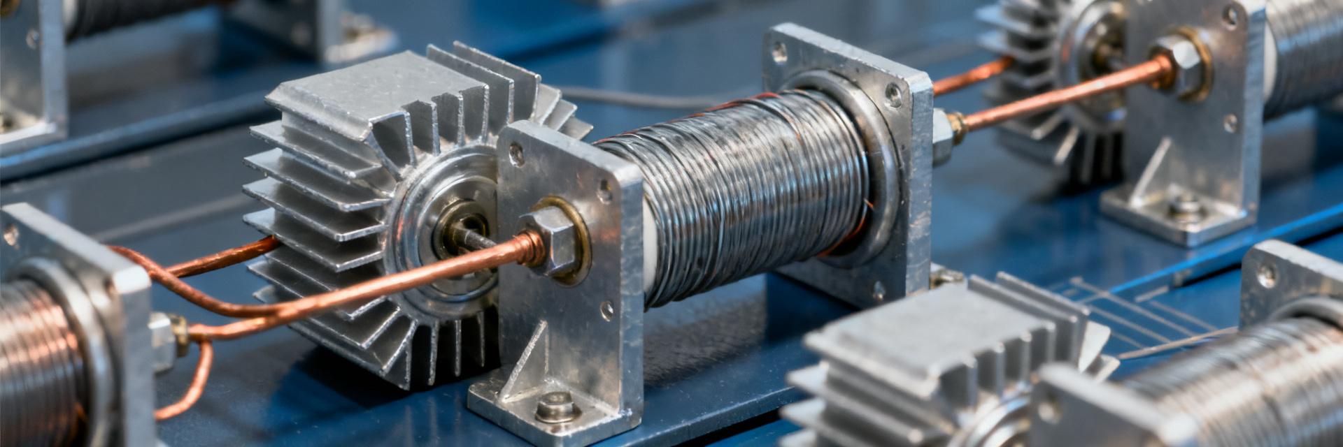
The nominal power of 300W is not unconditionally applicable. The actual load-bearing capacity of metal clad wirewound resistors follows a strict derating curve; for every 10°C increase in case temperature, the usable power typically drops by 8% to 12%. A common mistake made by engineers is directly equating the nominal power to the design margin, ignoring the compression effect of cooling conditions on the power boundary.
Nominal Power vs. Actual Operating Power
The 300W rating of the ULV300 series is based on standard cooling conditions: case temperature ≤ 75°C and natural convection environment. When the device is integrated into a sealed chassis or a high-temperature industrial site, the actual usable power may drop to the 180W-220W range. It is recommended to reserve a 30%-50% power margin rather than simply matching the nominal value.
Impact Factor of Cooling Conditions on Power Derating
Forced air cooling can increase the power coefficient to 1.3-1.5 times, but air duct resistance and noise costs must be calculated. Under natural convection conditions, the mounting orientation (vertical/horizontal) can affect thermal resistance by up to 15%-20%. The introduction of thermal simulation tools (such as Flotherm) has become a standard process for high-reliability design.
Parameter 2: Resistance Range and Tolerance Class—Coverage Logic from Milliohms to Kilohms
The ULV300 series covers a wide resistance range from 0.1Ω to 100kΩ, but the manufacturing processes differ significantly across different resistance segments. The low-resistance segment (<1Ω) utilizes manganin or constantan wire, focusing on current sensing functions; the medium-to-high resistance segment prioritizes meeting power dissipation requirements.
Selection Matching of E24/E96 Standard Resistance Series
Conventional applications prioritize the E24 series (±5% tolerance), which offers controllable costs and stable lead times. Precision sensing scenarios require upgrading to the E96 series (±1%), but must accept a 15%-25% unit price premium and longer lead times. Non-standard customized resistance values will significantly increase MOQ and tooling costs.
Cost-Performance Trade-offs between ±1% and ±5% Tolerances
The choice of tolerance class should return to the essence of circuit function: for power-type applications such as pre-charge resistors and braking resistors, ±5% tolerance completely meets requirements; for signal chain scenarios like current feedback and voltage division, investing in ±1% or even ±0.5% tolerance yields clear returns. Avoid paying hidden costs for unnecessary precision.
Parameter 3: Temperature Coefficient of Resistance (TCR)—Core Indicator of High-Temperature Stability
TCR characterizes the relative drift rate of resistance with temperature change and is a key parameter for measuring the thermal stability of a resistor. The ULV300 series offers two specifications, ±50 ppm/°C and ±100 ppm/°C, and selection should be comprehensively determined based on the operating temperature range and signal precision requirements.
Application Scenario Demarcation between ±50 ppm/°C and ±100 ppm/°C
When the operating temperature span exceeds 80°C or the resistance tolerance requirement is ≤ ±1%, the ±50 ppm/°C specification becomes a necessary configuration. Typical scenarios include: outdoor PV inverters, electric vehicle motor controllers, and high-power UPS. For internal braking resistors in general industrial frequency converters, ±100 ppm/°C can typically meet the requirements.
Quantified Impact of TCR on Sensing Circuit Precision
Taking a 100°C temperature rise and a 100Ω nominal resistance as an example: a ±100 ppm/°C specification generates a ±1% resistance drift, which, when superimposed with the initial tolerance, can cause the total error to exceed ±2%. High-precision current sensing circuits must execute an error budget superposition analysis of TCR and initial tolerance, rather than evaluating a single parameter in isolation.
Parameter 4: Thermal Resistance and Cooling Design—Core Advantages of Metal Clad
The core value of aluminum clad packaging lies in reducing the thermal resistance (Rth) to the range of 0.15-0.25°C/W, far lower than the 0.5-1.0°C/W of ceramic cores or plastic molded structures. This feature makes it possible for the ULV300 series to achieve high power density in compact spaces.
The Ternary Relationship of Case Temperature - Ambient Temperature - Power
Steady-state thermal equilibrium equation: T_case = T_ambient + P × Rth. When the ambient temperature is 60°C, the dissipated power is 250W, and the thermal resistance is 0.2°C/W, the case temperature will reach 110°C, which exceeds the life guarantee temperature of most electrolytic capacitors. System-level thermal design must establish a coupled thermal model of the resistor and its peripheral components.
Selection Differences under Forced Air Cooling and Natural Convection
Forced air cooling (3-5 m/s) can reduce the equivalent thermal resistance by 40%-60%, but introduces a single point of failure risk from fan failure. High-reliability designs tend to adopt natural convection solutions, achieving power sharing by increasing the heatsink area or using parallel redundant resistors. The bracket mounting structure of the ULV300 series reserves mechanical interfaces for heatsink expansion.
Parameter 5: Pulse Load Capability—Safe Boundaries for Short-Term Overload
The pulse capability of wirewound resistors depends on the thermal mass and the transient heat capacity of the resistive wire. The ULV300 series can withstand millisecond-level pulses of up to 10 times the rated power, but the repetition frequency and duty cycle will significantly affect lifetime expectancy.
Single-Pulse Energy and Repeat-Pulse Lifetime Evaluation
The failure mode of a single pulse is resistive wire fusing, and the energy threshold can be found via the I²t curve. Repetitive pulses induce cyclic thermal stress fatigue, and MTBF drops exponentially with pulse frequency. It is recommended to apply a power derating factor of 0.3-0.5 under pulse operating conditions and perform accelerated aging verification.
Typical Operating Conditions Comparison between Pre-charge Circuits and Braking Resistors
| Application Scenario | Pulse Characteristics | Selection Key Points |
|---|---|---|
| Pre-charge Resistor | Single or low-frequency, high energy | Focus on single-pulse I²t, no repeat life requirement |
| Braking Resistor | High-frequency repetitive, medium-to-low energy | Calculate average power and thermal cycle life |
Parameter 6: Dielectric Strength and Safety Certifications—Admission Thresholds for High-Voltage Systems
The insulation performance of metal clad resistors determines their suitability in high-voltage systems. The ULV300 series features a standard dielectric strength of 2500VAC/1min, meeting basic isolation requirements, but the differences between functional insulation and protective insulation levels must be strictly distinguished.
Interpretation of the 2500VAC/1min Test Standard
This test voltage corresponds to overvoltage category II, pollution degree 2 conditions in IEC 60664-1. When applied in 1500VDC PV systems or high-voltage energy storage platforms, it needs to be upgraded to 4000VAC specifications or adopt a series voltage divider architecture. The DC equivalent of the test voltage is approximately 1.4 times the AC RMS value.
Global Market Access Strategies with UL/VDE/CQC Certifications
The North American market mandates UL508/UL840 certification, the EU requires compliance with EN 60950-1 or EN 62368-1, and the Chinese market requires voluntary CQC certification. The multi-certification coverage of the ULV300 series can simplify BOM management for global projects, but it is necessary to verify the correspondence between specific certificate numbers and product models.
Parameter 7: Mechanical Structure and Mounting Methods—The Final Step of Engineering Implementation
The impact of mounting orientation on cooling efficiency is often underestimated. The ULV300 series offers three mechanical configurations: vertical, horizontal, and bracket mounting. Selection must balance PCB layout, air duct design, and maintenance convenience.
Cooling Efficiency Comparison of Vertical/Horizontal/Bracket Mounting
Vertical mounting utilizes the chimney effect to enhance natural convection, yielding the lowest thermal resistance but occupying significant height; horizontal mounting is suitable for low-profile chassis, requiring full contact between the bottom and the cooling surface; bracket mounting supports external heatsink expansion, making it the preferred choice for high-power-density scenarios. Measured data show that under the same operating conditions, the case temperature difference among the three orientations can reach 15-25°C.
Compatibility Design of Lead Specifications and PCB/Chassis Fixing
Standard lead specifications are 12AWG-10AWG tinned copper wires, meeting the current-carrying capacity for 300A-level transient currents. PCB mounting requires evaluating pad thermal stress and copper foil peel strength; chassis mounting requires attention to mounting torque (typically 2.5-3.5 N·m) and ground continuity. For vibration environments (such as rail transit), it is recommended to add locking adhesive or anti-loose washers.
Key Summary
- Power derating is the primary principle: The 300W nominal value must be adjusted based on cooling conditions; an actual design margin of ≥30% is recommended, and forced air cooling can increase the factor to 1.3-1.5 times.
- Tolerance and TCR must be evaluated jointly: For high-precision sensing scenarios, prioritize ±1% combined with ±50 ppm/°C; for power-type applications, ±5% and ±100 ppm/°C are more cost-effective.
- Pulse conditions must distinguish between single and repetitive: For pre-charge resistors, focus on single-pulse energy; for braking resistors, calculate thermal cycle life and average power.
- Mounting orientation affects cooling efficiency: The case temperature difference among the vertical, horizontal, and bracket structures can reach 15-25°C, requiring coordinated optimization with the air duct design.
- Safety certifications must match target markets: Multi-certification coverage of UL/VDE/CQC can simplify the global supply chain, but the correspondence between certificates and models must be verified.
Frequently Asked Questions
How to calculate the actual usable power of the ULV300 series 300W wirewound resistor?
Actual usable power = Nominal power × Derating factor, where the derating factor is determined by the case temperature. Under natural convection with a case temperature of 75°C, the factor is 1.0; at a case temperature of 100°C, it drops to 0.6-0.7. It is recommended to determine the case temperature under specific operating conditions through thermal simulation or actual measurement, and then back-calculate the safe power boundary.
How should the priorities of TCR (temperature coefficient of resistance) and tolerance be ranked in wirewound resistor selection?
For wide temperature range applications (ΔT > 80°C), controlling TCR takes priority; for narrow temperature range, high-precision applications, initial tolerance takes priority. Typical strategy: first filter candidate models by tolerance, then verify if the TCR meets the error budget across the entire temperature range, and finally perform cost trade-offs.
How to predict the lifetime of metal clad wirewound resistors under pulse operating conditions?
It is necessary to obtain the pulse power curve and cycle life data from the manufacturer. Engineering approximation method: calculate the equivalent average power under the pulse duty cycle to ensure it does not exceed 50% of the rated value; simultaneously verify if the single pulse peak is below the transient limit. Final reliability must be verified through accelerated aging tests.
How much does the mounting method of the ULV300 series affect heat dissipation?
Under the same operating conditions, vertical mounting has the lowest thermal resistance due to the chimney effect, horizontal mounting increases it by 10%-15%, and bracket mounting with an external heatsink can optimize it by 30%-50%. Specific values depend on the heatsink specifications and air duct design; it is recommended to determine this in combination with CFD simulation or actual measurement.


