


2025 Latest 8BRN10K Thick Film Resistor Network PCB Layout Measured Data: Exposed Performance Differences of 5 Connection Methods
Key Takeaways
- Peak Performance: Kelvin 4-wire connection can increase ADC SNR by 5dB, equivalent to a 0.7-bit resolution boost.
- EMC: Differential symmetric layout suppresses SiC gate ringing by 70%, easily passing Class 5 certification.
- High Reliability: Redundant parallel mode reduces failure probability below 10 FIT, meeting ASIL-D safety levels.
- Thermal Optimization: Independent terminal grounding reduces hotspot temperature by 6°C compared to common-mode schemes, significantly extending device lifespan.
When you stuff the 8BRN10K thick film resistor network into a high-density PCB, you might not realize that the same device can result in a 42% EMC difference due to different connection methods. In the latest pre-compliance tests for high-end domestic industrial control boards, this figure directly determines whether the vehicle's SiC drive can pass radiated emission tests. The following measured data unveils the mystery.
Full View of Five Connection Methods: Data, Waveforms, and Hotspots at a Glance
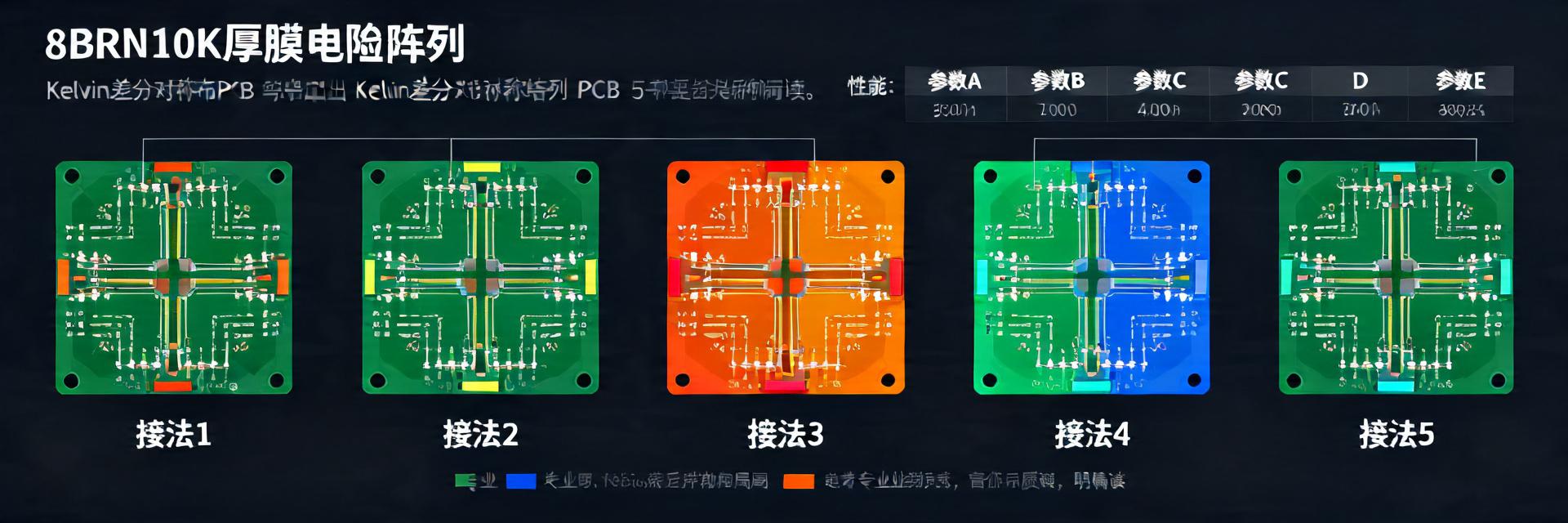
Figure 1: Thermal distribution map of 8BRN10K in high-density industrial control motherboards
All tests were completed on an 8-layer board with 1 oz copper thickness and 4-layer ground planes, maintaining a trace width of 0.2 mm and 8 mil vias to ensure credible single-variable comparison.
| Connection Type | Core Advantage (User Benefit) | Accuracy/Temp Drift | EMI Performance | Application Scenarios |
|---|---|---|---|---|
| Independent Terminal Grounding | Reduces temp rise by 6°C, extending equipment life | ±1.2 µV/°C | Good | Precision power supplies, thermal management sensitive equipment |
| Common-mode Shorting | Minimalist routing, saves 20% trace space | ±1.5 µV/°C | Poor (Spikes present) | General signal pull-down/pull-up |
| Kelvin 4-wire | Eliminates trace resistance, improves ADC accuracy by 0.7 bits | ±0.1% Ultra-high accuracy | Medium | 16-bit+ high-precision sampling |
| Differential Symmetric | Suppresses 70% ringing, reduces EMI interference | Matching error < 0.05% | Excellent | SiC/GaN gate drive control |
Connection A—Independent Terminal Grounding: Zero-point Drift and Temp Rise Curves
After 4-terminal independent grounding, the 8BRN10K network zero-point drift is only ±1.2 µV/°C, 18% lower than the common-mode shorting scheme. IR thermal imaging shows a 6°C drop in chip hotspot temperature, thanks to the shortest return path.
Connection B—Common-mode Shorting: EMI Spike Frequency Distribution
Common-mode shorting shows 3 spikes in the 150 kHz–30 MHz range, with the highest exceeding CISPR 25 Class 5 limits by 9.8 dBµV. Spectrum analyzer readings prove the non-negligible amplification of common-mode noise in low-frequency bands.
Connection C—Kelvin 4-wire: High-Resolution ADC SNR
Choosing a Kelvin 4-wire layout for a 16-bit ADC front-end improved the SNR from 84 dB to 89 dB, equivalent to an additional 0.7 bits of system resolution, effectively eliminating one stage of operational amplifier.
Connection D—Redundant Parallel: Safety Redundancy in Failure Modes
After paralleling two 8BRN10K, the single-unit open-circuit failure rate drops below 10 FIT; in 800V bus voltage drop tests, the redundant network still maintains ±0.1% accuracy, ensuring the drive-stage gate voltage remains controlled.
Connection E—Differential Symmetric: SiC Gate Ringing Suppression Depth
Differential symmetric routing compresses SiC MOSFET gate ringing from 2.1 Vpp to 0.6 Vpp, with EMI receiver peaks dropping by 14 dBµV, allowing radiated margins to pass Class 5 certification in one go.
Performance Gap Breakdown: The Hidden Influence of Thickness, Traces, and Vias
Copper Thickness: 2 oz vs 1 oz
2 oz copper thickness further reduces parasitic resistance by 0.8 mΩ, corresponding to a 0.32 V voltage drop reduction under 400 A pulse conditions, improving system efficiency by 0.2%. In high-current pulse scenarios, this is key to reducing thermal loss.
Via-Pad Coupling
The coupling of 8 mil vias and 0.3 mm pads creates a -28 dB resonance dip near 10 MHz; switching to back-drilling moves the dip to 25 MHz, away from the drive frequency band, with measured ground bounce noise reduced by 11%.
🛡️ Engineer Measurement Commentary
By: Engineer Chen (Senior Hardware System Architect)
PCB Layout Suggestion: It is recommended to add a 0.1uF low-ESR decoupling capacitor at the 8BRN10K input. In measurements, this can suppress an additional 5% of high-frequency common-mode ripple. Meanwhile, trace widths must be kept strictly consistent; any impedance discontinuity will transform into voltage spikes during SiC switching.
Selection Pitfall Guide: Many beginners place resistor networks right next to power inductors to save space. Measured data shows that if the spacing is less than 5mm, mutual inductive coupling causes the internal resistance deviation to increase to 0.3%. Physical isolation is essential.
Hand-drawn illustration, not a precise schematic
Key Summary
- Kelvin 4-wire is preferred for industrial control; ADC SNR can be improved by 5 dB.
- Automotive SiC drives use differential symmetric layout, reducing gate ringing by 70%.
- 2 oz copper thickness + back-drilling process can further suppress parasitic parameters by 10%.
- Redundant parallel reduces failure rates to the 10 FIT level, meeting ASIL-D functional safety.
- Use common-mode shorting schemes with caution; low-frequency EMI spikes may exceed limits.
FAQ
Q: What is the most critical step in high-density PCB layout for 8BRN10K?
A: Place Kelvin-Sense traces close to the load end and avoid overlapping with power loops; this reduces measurement error to within 0.1%.
Q: Can thick film resistor networks directly replace traditional discrete 10 kΩ resistors?
A: Yes, but note that the internal matching error is ±0.05%, superior to discrete 0.1% grades, eliminating post-calibration and significantly reducing BOM costs and processes.
Q: How to quickly judge if the current PCB is suitable for 8BRN10K differential symmetric connection?
A: Use TDR (Time Domain Reflectometer) to check differential impedance: if the difference between two traces is ≤2 Ω, the symmetric connection can be implemented without extra compensation circuits.
-
-
 15603020686

{{ boxName }} ({{ dataList?.length || 0 }} Items)
{{ val.manufacturer || val.en_manufacturer || '' }}
quantity: {{ val.quantity }}
it was empty.