


In power supply protection design, the selection of Metal Oxide Varistors (MOVs) holds hidden complexities. More than 70% of early failures stem from atypical parameters overlooked during selection.
In power supply protection design, the selection of Metal Oxide Varistors (MOVs) like the MPM10011002AT0 may seem simple, but it actually holds hidden complexities. Over 70% of early failure cases do not stem from quality issues with the components themselves, but rather from engineers overlooking several atypical yet critical parameters during selection. This article will address these pain points directly, providing a deep analysis of the key parameters most easily ignored in the MPM10011002AT0 selection process, helping you build more reliable and longer-lasting circuit protection solutions.
Revealing Misconceptions: Why Conventional Selection Logic Leads to "Pitfalls"?
When selecting the MPM10011002AT0 for the first time, many engineers habitually prioritize its nominal voltage and surge current capacity. This selection method based on static parameters often overlooks the dynamic complexities in real-world applications, sowing the seeds for future system stability issues.
Focusing Only on Nominal Voltage and Surge Current Capacity
Selecting based solely on the maximum continuous operating voltage and nominal surge current capacity from the datasheet is a common trap. Voltage fluctuations, high-frequency noise, or combined stresses in actual circuits can far exceed nominal test conditions.
Ignoring Differences in Dynamic Stress Across Application Scenarios
Surge waveforms (such as 8/20μs lightning strikes vs. 10/1000μs switching surges), frequency of occurrence, and ambient temperatures vary greatly across different application scenarios. Ignoring these differences can lead to components being in an overstressed state.
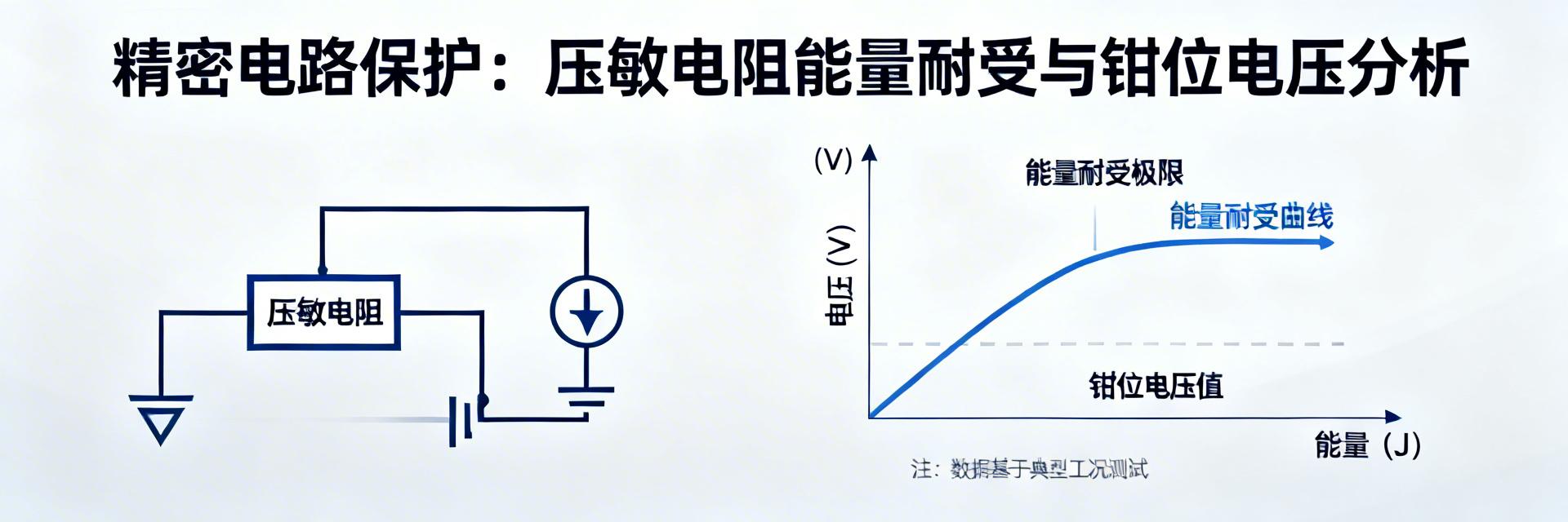
Deep Parameter Analysis: Energy Rating
The energy rating is a core indicator for measuring the MPM10011002AT0's ability to absorb single or multiple surge energy events without damage. It directly determines the component's survivability in real-world overvoltage events.
Understanding the Fundamental Difference Between "Single Pulse" and "Multiple Pulse" Energy
Datasheets typically provide maximum single pulse energy and multiple pulse energy values. The key is that the energy rating under multiple pulses is significantly reduced because the initial pulse causes internal micro-damage and temperature rise.
How to Calculate and Match Energy Requirements Based on Actual Surge Waveforms
During selection, the expected surge waveform should be plugged into the formula E ≈ Vc × Ip × t (where Vc is the clamping voltage) for estimation, with a safety margin of at least 20%-30% reserved.
Deep Parameter Analysis: Clamping Voltage and Clamping Ratio
Clamping voltage refers to the maximum voltage across the MPM10011002AT0 under a specified surge current. It is the last line of defense for protecting downstream precision components.
| Analysis Dimension | Impact on Downstream Components | Selection Advice |
|---|---|---|
| Implicit Threat of Vc Values | Vc increases under extreme surges, potentially exceeding the withstand voltage of ICs/MOSFETs. | Calculate the actual residual voltage under maximum surge current. |
| Non-linear Variations | If the current increases 10-fold, the clamping voltage may rise by 20%-50%. | Consult V-I curve families to evaluate the safety window. |
Deep Parameter Analysis: Aging Characteristics and Lifetime Prediction
The performance of varistors gradually degrades over time and with the frequency of stress endurance; the aging process must be considered proactively.
- • Leakage Current Evolution Patterns: As aging progresses, leakage current gradually increases, leading to higher static power consumption and temperature rise. This can easily create a vicious cycle in high-temperature environments.
- • Lifetime Assessment Methods: Referencing MIL-STD or IEC standards, compare the average annual surge frequency against lifetime curves to ensure the service life exceeds the product's design life.
Practical Selection Process and Verification Checklist
Five-Step Selection Method
Key Summary
- • Thinking Beyond Nominal Values: Gain a deep understanding of energy tolerance, clamping voltage non-linearity, and aging patterns.
- • Dynamically Matching Application Scenarios: Perform dynamic calculations based on specific surge waveforms, frequency, and environmental stress.
- • Systematic Process and Verification: Ensure long-term system reliability through the five-step selection process combined with thermal simulation verification.

